TL431 Voltage Regulator Detailed Guide
2024-04-17
15998
TL431 is a Three-Terminal Controlled Precision Reference Integrated Chip with Good Temperature Stability. Due to its High Accuracy, Low Quiescent Current, and Output Noise, it is Widely Used in a Variety of Electronic Devices, such as Automatic Control, Power Management, and Power Conversion. To Help Everyone Have a Better Understanding of TL431, This Article has Compiled Relevant Information About TL431. Come and Take a Look.
Catalog
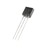
Figure 1: TL431
What Is TL431 Regulator?
TL431 is a 2.50V to 36V Adjustable Precision Shunt Regulator Jointly Produced by Texas Instruments Incorporated (TI) and Motorola Incorporated in the USA. It has the Capability of Adjustable Current Output and Serves as a Reference Voltage Source. The TL431 Series Includes TL431C, TL431AC, TL431I, TL431AI, TL431M, TL431Y, Totaling Six Models. These Models Share an Identical Internal Circuit Structure with Only Minor Differences in Technical Indicators. Owing to Its Compact Size, Precision Adjustable Reference Voltage, and Large Output Current, the TL431 Can Be Used to Design a Variety of Regulators. Its Performance Characteristics Include Continuously Adjustable Output Voltage up to 36V, a Wide Operating Current Range from 0.1mA to 100mA, a Typical Dynamic Resistance of 0.22 Ohms, and Low Output Noise. Additionally, It has a Maximum Input Voltage of 37V, a Maximum Operating Current of 150mA, an Internal Reference Voltage of 2.5V, and an Output Voltage Range from 2.5V to 30V.
Alternatives and Equivalents
Main Features of TL431
High Accuracy
The Reference Voltage Accuracy of the TL431 Can Reach ±2 Percent or Higher, Enabling It to Provide Stable and Accurate Output Voltages Over a Wide Range of Voltages.
Good Dynamic Performance
TL431 Features Fast Dynamic Response. It Can Quickly Adjust the Output Voltage in Response to Power Supply Load Changes, Ensuring a Stable Power Supply Output.
Simplified Circuit Design
As the TL431 Integrates an Error Amplifier and a Reference Voltage Source, It Simplifies Circuit Design, Reduces Circuit Size, and Lowers Power Supply Costs.
Adjustable Output Voltage
The Output Voltage of the TL431 Can Be Adjusted Using Two External Resistors, Offering an Adjustment Range from 2.5V to 36V, Adequate for Various Power Supply Circuits.
TL431 Ratings
The Current, Voltage, and Wattage Ratings of Any Device Indicate Its Power Requirements, i.e., How Much Current and Voltage Are Sufficient for Its Operation. The Following Table Provides the Current, Power, and Voltage Ratings of the TL431.
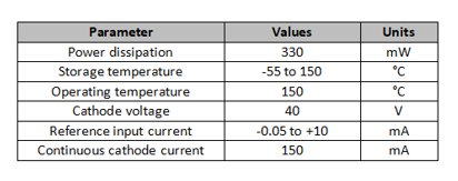
Figure 2: TL431 Parameter List
How to Measure the Quality of TL431?
To measure whether the performance of the TL431 is good, we need to identify its pins as the reference terminal, anode, and cathode. After confirming the pins, we can follow the steps below to measure. First, we adjust the range of the multimeter to the Rxlk block, connect the black pen to the anode, and the red pen to the cathode. What is measured at this time is the forward resistance of the TL431. Next, we interchange the test leads, that is, the black pen is connected to the cathode and the red pen is connected to the anode. At this time, infinite reverse resistance should be displayed. This means that when the current flows from the anode to the cathode, the TL431 can be turned on normally; and when the current flows from the cathode to the anode, the TL431 is turned off. Next, we still keep the multimeter range at the Rxlk block, connect the black pen to the reference terminal, and the red pen to the cathode. At this time, there should be no current flowing through it, that is, there is no indication on the meter. Then, when we touch the black pen with one hand and the anode with the other hand, the pointer should swing significantly. When this situation is met, the pin touched by hand is the reference terminal. The final step is to short-circuit the reference terminal and the anode, that is, allow current to flow from the reference terminal and the anode at the same time. In this case, if the black test lead is connected to the cathode and the red test lead is connected to the anode, there will usually be a smaller voltage drop; conversely, if the black test lead is connected to the anode and the red test lead is connected to the cathode, there will generally be a relatively large voltage drop. The principle of this measurement is based on the different voltage drops of the TL431 during forward and reverse conduction.
What Can It Be Used For?
Voltage monitor
Crowbar circuit
Shunt regulator
Precision current limiter
High-current shunt regulator
PWM converter with reference
Precision high-current series regulator
How to Distinguish the Three Pins of TL431?
The TL431 has three pins, which are the reference terminal, anode, and cathode. To distinguish these three pins, we can arrange them from left to right with the logo facing us. Specifically, the reference terminal is the pin used to input the reference voltage; the anode is the pin through which current flows; and the cathode is the pin from which current flows out. In practical applications, the cathode is usually connected to the positive pole of the power supply through a current-limiting resistor, while the anode is connected to the negative pole of the power supply. Its pin diagram is as follows:
Pin 1 (Reference): This pin sets the voltage rating of the Zener diode.
Pin 2 (Anode): Anode of the equivalent Zener diode
Pin 3 (Cathode): Cathode of the equivalent Zener diode
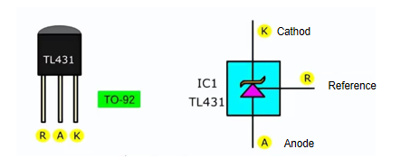
Figure 3: TL431 Pin Diagram
Structure and Working Principle of TL431
The TL431 is a three-terminal adjustable shunt regulator with excellent stability. It is often used as an adjustable voltage reference. Its external structure consists of three pins: cathode, anode, and reference voltage. The internal structure is as shown in the figure. In most applications of the TL431, the anode is usually connected to ground, and a portion of the cathode current flows through the mirror current source in the lower left corner of the block diagram. The voltage drop generated by this current on the resistor, plus the voltage drop between the base B and emitter E of the transistor, together constitute the reference voltage of 2.5V. The intermediate stage structure of the TL431 is equivalent to a differential amplifier circuit, while its output stage adopts a Darlington structure. Therefore, the TL431 not only has an internally integrated voltage reference function but also integrates the function of an operational amplifier circuit.
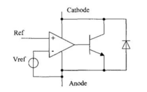
Figure 4: TL431 Functional Structure
According to its function, the TL431 consists of an internally integrated 2.5V reference voltage, a differential op-amp, and an open collector transistor. A simplified diagram of the TL431 is shown below. When the voltage on the reference voltage pin is lower than the internal reference voltage of 2.5V, the op-amp outputs a low level, at which time the triode is in the off state, no current flows in the TL431 (ignoring the tiny leakage current); and when the voltage on the reference voltage pin is higher than the internal reference voltage, the op-amp outputs a high level, the triode conducts and draws current from the cathode, and enters into saturation region rapidly. Only when the voltage on the reference voltage pin is very close to the reference voltage, the triode will work in the amplification area, from the cathode to extract a constant current. The analysis shows that in switching power supply, the original structure which requires discrete reference voltage and op-amp for feedback can be well replaced by TL431.
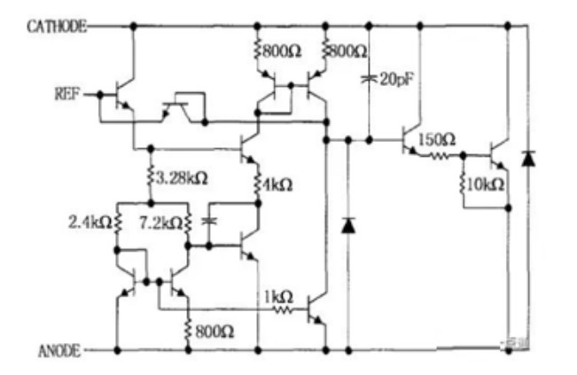
Figure 5: TL431 Internal Structure Circuit
Precautions for TL431 Application
When using the TL431, we should pay attention to the following aspects.
Pay Attention to the Current Size
The minimum current flowing through the TL431 must be kept above 1mA, otherwise, it will lose its voltage regulation performance. At the same time, the maximum current cannot exceed 100mA to avoid damaging the TL431.
Minimum Holding Current and Minimum Cathode Voltage
Since the internal reference voltage Vref of the TL431 is maintained by the cathode current, and this current must be higher than a certain threshold to ensure normal operation, special attention needs to be paid during application: when the output pole of the TL431 is in the cut-off state, the cathode still needs to maintain a holding current greater than 0.2mA; when the output pole is in saturation, the voltage between the poles must be at least greater than 2.2V to ensure that the TL431 can operate normally.
Pay Attention to Power Consumption
Taking the common TO-92 package as an example, the maximum power consumption of TL431 is 0.7W. In fact, the power consumption P of TL431 in the circuit can be calculated by the formula P=Vo*I, where Vo is the output voltage and I is the current through TL431. Therefore, when the output does not exceed 5V, the TL431 can output a maximum current of 140mA; when the output voltage is 7V, it can only output a current of 10mA due to power consumption limitations. Typically, the power consumption of the TL431 ranges from 0.5W to 1.2W. When it works under high temperature, high voltage or high current conditions, we must pay special attention to ventilation, heat dissipation and the safety of the overall circuit to prevent performance degradation or damage caused by excessive power consumption.
Pay Attention to the Selection of Sampling Resistors R1 and R2
When selecting materials and laying out, we should give priority to precision resistors of the same type with small temperature coefficient, low noise, and large power capacity to ensure stability and reliability. According to the formula Vo=2.5*(1+R1/R2), when Vo is a maximum of 36V, we can calculate that the maximum ratio of R1 to R2 is 13.4, that is, the maximum value of R1 should be 13.4 times that of R2. In addition, due to the high open-loop gain and fast response speed of TL431, when the sampling point (that is, the connection point of R1 and R2) is far away from the two poles, the circuit is prone to overshoot self-excitation. Therefore, when designing and using, we need to pay special attention to the location of the sampling point to avoid this situation.
Frequently Asked Questions [FAQ]
1. Is TL431 a Zener Diode?
Yes, it is a programmable Zener diode. The output voltage ranges from 2.5 volts to 36 volts. The output voltage tolerance will be ±4 percent. The output current or sink current ranges from 1 mA to 100 mA.
2. What is the Difference Between TL431 and TLV431?
The TL431 is the original standard shunt voltage reference. The TLV431 is a lower voltage reference option of the TLV but also has some different specifications.
3. What is the Function of TL431?
The TL431 in an open-loop configuration is often used as a voltage comparator, undervoltage monitor, overvoltage monitor, window voltage detector, and many other types of uses. The TL431 is a shunt voltage reference commonly used for these applications.
4. What is the Equivalent of a TL431 Transistor?
When the TL431 is damaged, if there is no replacement of the same model, it can be directly replaced with KA431, μA431, LM431, YL431, S431, etc. TL431 suffix letters indicate product level and operating temperature range.
5. What are the Characteristics of TL431?
The TL431 and TL432 devices are three-terminal adjustable shunt regulators, with specified thermal stability over applicable automotive, commercial, and military temperature ranges. The output voltage can be set to any value between Vref (approximately 2.5 V) and 36 V, with two external resistors.
function test. The highest cost-effective products and the best service is our eternal commitment.
Hot Article
- Are CR2032 and CR2016 Interchangeable
- MOSFET: Definition, Working Principle and Selection
- Relay Installation and Testing, Interpretation of Relay Wiring Diagrams
- CR2016 vs. CR2032 What’s the difference
- NPN vs. PNP: What's the Difference?
- esp32 vs stm32: which microcontroller is better for you?
- LM358 Dual Operational Amplifier Comprehensive Guide: Pinouts, Circuit Diagrams, Equivalents, Useful Examples
- CR2032 VS DL2032 VS CR2025 Comparison Guide
- Understanding the Differences ESP32 and ESP32-S3 Technical and Performance Analysis
- Detailed Analysis of RC Series Circuit
 Resistor Symbol Guide
2024-04-18
 LM358P Op Amp: Description, Features, Package, Usage, Equivalents
2024-04-17
Hot Part Number
 HHXC630ARA330MJA0G
 GMK316AB7106KL-TR
 C1005JB1C473M050BA
 CC1206KKX5R6BB226
 CC0603BRNPO9BN2R4
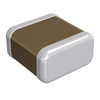 GRM0337U1H9R7CD01D
 TWAE687M030CBEZ0700
 TLJR476M010R3200
 DSA300I200NA
 R5F100PJAFB#V0
- MAX3668EHJ
- AP2152ASG-13
- V375B28H300BN
- MCF51JE128CLK
- RT0402DRE0722RL
- 2MBI300U4D120-50
- SN761666DGKRG4
- CD74HC40105M96G4
- NC7SZ04M5X
- S912XEP100BMAGR
- BQ24004PWP
- ADM1385ARSZ
- ADS1256IDBTG4
- LT6700CS6-3#TRMPBF
- LB11620T-TLM-E
- LT1769CGN#TRPBF
- LT8410IDC-1#TRMPBF
- T494D335K050AT
- AT25F1024N-10SU-2.7
- CY2510ZC-1T
- HD6437065AA25FV
- IRU3037CQ
- M13S32321A-6L
- M86200G-12
- PF38F5070M0Y1V0ES
- R2A20117SP
- TMS320TCI100BCLZ
- CH7305A-T
- CSP1089LT11
- NT66P14L
- QS5LV919-100Q
- MAX24405EXG
- AIC1748BH-33GV5TR
- MST9259H-LF-165
- EFR32MG13P732F512IM32-DR
- Z0843004PSCZ80 CTC
- LTM4638EY#PBF
- PINA821IDR
- S14B-PUDSS-1