At the heart of electrical systems lie relays, not just mere components but the very linchpins that connect and disconnect circuits, embodying the essence of complex electrical control functions. This article delves deep, aiming to dissect both the basic structure and the intricate operating mechanism of relays. We will gradually disassemble the specific internal structures of 4 pin relays and 5 pin relays through an in-depth analysis of the 4 pin relay wiring diagram and 5 pin relay wiring diagram. It's a journey through their diverse applications across fields, with a spotlight on the automotive industry's reliance on them. Our exploration will be thorough: dissecting the nuances of various relay types, with a special focus on the unique attributes and uses of 5 pin relays. Expert guidance awaits – on installation, configuration, and testing. In these details, a broader picture emerges. Understanding relays unravels the complexities of modern technology. Their role? Indispensable, particularly in the intricate web of automotive electrical systems.
Catalog
Figure 1: Relay
Relays, intricate electromechanical devices, control their mechanical contacts through electrical signals to connect and disconnect circuits. This is no mere switch; it's a precision tool. It's sensitive to minuscule fluctuations in electrical signals, and governs a larger current path. Their application scope is vast, touching everything from daily life to cutting-edge technology.
In automotive electrical systems, relays are pivotal. They manage diverse functions: lighting, starting systems, airbag deployment, and beyond. This enhances performance and safety, injecting intelligence into vehicles.
Home automation, another key relay domain, leverages them for lighting, heating, ventilation, and security. Their reliability and adaptability boost efficiency and user-friendliness.
In industrial settings, relays are central to automation control and process monitoring. They safeguard mechanical equipment and monitor system status. Their widespread use in test and measurement gear enables precise electrical signal control.
Automotive relays are crucial. They allow small switches to safely control large circuits, preventing overload damage. This boosts system safety and stability.
Relays also elevate circuit flexibility and reliability. In complex systems like automated factories and precision medical gear, their precision ensures operational accuracy and long-term stability.
Among various relay types, electromagnetic ones are significant. Subcategories include armature attraction and induction types, each with unique traits and applications. For instance, armature attraction relays excel in fast-response scenarios, while inductive ones shine in complex control systems.
For professionals, understanding relay principles and wiring is key. Wiring diagrams are crucial for electrical engineers, technicians, and maintenance personnel. They aid in troubleshooting and optimizing performance, providing deep insights into relay functions and connections.
Relays are indispensable in modern electrical systems. Their versatility, reliability, and adaptability make them vital across industries – from automobiles and home automation to industrial controls.
Relay, an advanced electromechanical switching device, fundamentally differs from traditional physical switches. In everyday life, manual switches control circuit operations. Relays, however, use electrical signals, boosting control accuracy and flexibility.
Central to a relay are two components: an electromagnet and an actuator. The electromagnet, an iron core wrapped in wire, works in tandem with an actuator, typically housing mechanical contacts. Upon receiving a signal, the electromagnet's current-induced magnetic field moves the actuator. This movement switches the circuit's contacts, alternating between states like 'normally closed' and 'normally open.'
This electromagnetic process allows relays to respond to minute electrical signals, controlling larger currents. Such functionality not only enhances the relay's circuit control flexibility but also broadens its application scope and efficiency. For instance, in automation systems, relays respond to sensor signals, control hefty mechanical equipment, and execute complex logic.
The relay's design enables rapid state switching, ensuring stable performance and longevity. It's an ideal component for automatic control systems, communication gear, and household appliances.
Relays excel not just in signal control flexibility but also in providing precise, reliable control in intricate systems. Their unique mechanism cements their role as indispensable in modern electrical control systems.
The relay's unique design lies in the isolation between its switching components (actuator and contacts) and the activation mechanism (coil and electromagnet). This not only bolsters reliability and safety but also empowers it to control high-current devices effectively. Particularly crucial is this design when low-voltage devices, like microcontrollers, are tasked with managing high-current devices.
Relays are extensively utilized in the automotive industry, playing a critical role in vehicles' electrical systems. They handle high-current components: headlights, heater/cooling systems, audio systems, and more. By incorporating relays, these high-current components are not only efficiently managed, but the usage of copper wire is also markedly reduced. This optimizes the vehicle's energy efficiency and cost-effectiveness.
Furthermore, relays find widespread use in household appliances and industrial automation. In home appliances, they manage currents in large devices such as air conditioners and refrigerators. In industrial automation, they control hefty mechanical equipment like motors and pumps, precisely managing start and stop functions to ensure efficient, safe operation of production lines.
Relays are also pivotal in new energy sectors like solar and wind energy systems. Here, they regulate power distribution and management, ensuring efficient energy utilization and stable system operations.
Having become an indispensable component in modern electrical systems, relays showcase their efficiency and unique design across diverse fields. Be it in automobiles, home appliances, or industrial automation, their advantages and significance are evident in a wide array of applications.
In the intricate realm of automotive electrical systems, a profound grasp of relay terminology and their multifaceted functions stands as a cornerstone for their correct installation and seamless operation. Grasping these concepts does more than just shed light on the relay's working principles; it lays the groundwork for essential technical guidance in repair and maintenance tasks.
Central to a typical automotive relay are five pivotal pins: two coil pins, a common (COM) pin, a normally open (NO) pin, and a normally closed (NC) pin. These pins, each with a distinct role and configuration, collectively orchestrate the relay's functionality and efficiency.
Coil Pins: Serving as the bridge to the control circuit, these pins, when energized, generate an electromagnetic field. This field, in turn, triggers the relay's switching mechanism—a dance of current and control.
Common (COM) Pin: The COM pin stands as the relay's primary power conduit, typically linked to a power source, like a 12V supply. It is pivotal in distributing current to the relay's other pins.
Normally Open (NO) Pin: In its default state, without a control signal, the NO pin remains isolated from the COM pin. Activation of the coil alters this state, connecting the NO and COM pins to enable current flow.
Normally Closed (NC) Pin: In contrast to the NO pin, the NC pin maintains a default connection with the COM pin in the absence of a control signal. Upon coil activation, this connection is severed, interrupting the current flow.
The configuration and functionality of these pins are not mere technicalities; they are the lifeblood of the relay's operation. Their arrangement and performance not only dictate how the relay manages current across different states but also significantly impact the relay's efficacy and dependability in practical scenarios. Consider, for instance, automotive electrical systems—where proper pin configuration allows relays to adeptly manage critical components like the vehicle's lighting, starter, and audio systems.
Thus, for professionals delving into automotive electrical repair and maintenance, an in-depth understanding of these terminologies and the relay's basic architecture is paramount. It transcends mere enhancement of maintenance efficiency and fault diagnosis. It's about elevating the performance and safety of the entire system—a responsibility of immense significance.
Commonly used pin numbers:
|
Pin Number
|
Description
|
|
85
|
Coil
|
|
86
|
Coil
|
|
87
|
Normally Open (NO)
|
|
87a
|
Normally
Closed (NC)
|
|
30
|
COM
|
In the nuanced world of automotive electrical systems, the classification and selection of relays are pivotal, directly impacting the system's functionality and efficiency. At a basic level, automotive relays bifurcate into two primary types: 4 pin and 5 pin relays. Though similar in function, the distinction lies in their pin configuration and intended application scenarios.
4 pin Relay: This variant encompasses two coil pins and two contact pins (normally open and general purpose). Utilized for simpler control tasks in vehicles, these relays are integral in managing systems like vehicle lighting or audio.
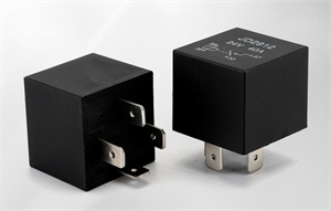
Figure 2: 4 Pin Relay
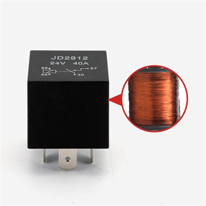
Figure 3: 4 Pin Relay

Figure 4: 4 Pin Relay
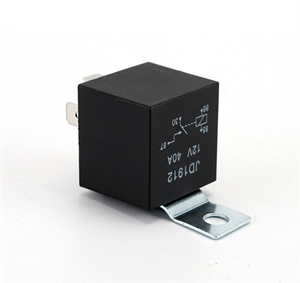
Figure 5: 4 Pin Relay
5 pin Relay: In contrast, the 5 pin relay introduces an additional "87a" or normally closed (NC) pin. This augmentation grants the relay heightened control versatility, tailoring it for more intricate systems such as airbag deployment or autonomous driving assistance.
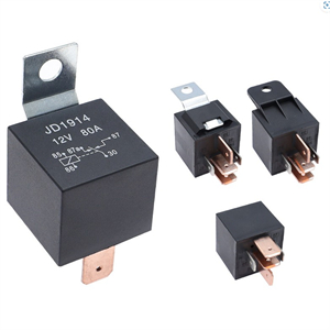
Figure 6: 5 Pin Relay
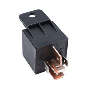
Figure 7: 5 Pin Relay
Furthermore, relays are also differentiated as Type A and Type B, based on the positioning of the COM (Common Purpose) pin.
Type A Relay: Here, the COM pin is initially linked to the normally closed pin, shifting to a normally open pin upon coil activation. Type A is optimal for contexts necessitating a default off state.
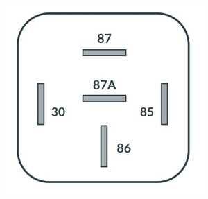
Figure 8: Type A Relay
Type B Relay: Inversely, Type B’s COM pin connects by default to the normally open pin, suitable for situations requiring a constant closed state.
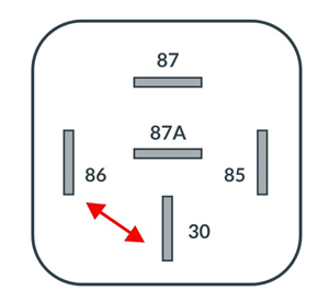
Figure 9: Type B Relay
Grasping the intricacies of these relay types, along with their distinct characteristics, is essential in selecting the appropriate relay for specific automotive applications. The right choice transcends mere operational efficiency; it bolsters system reliability and safety, ensuring a harmonious interplay within the vehicle’s electrical framework.
Grasping the intricacies of a relay's wiring diagram is not merely useful, but crucial. It's the cornerstone of proper installation and the key to a relay's efficient operation. These diagrams do more than just guide technicians in connecting relays; they unravel the mysteries of the relay's role and its logical connections within the broader electrical landscape. It's a dance of comprehension and application.
The value of these diagrams extends beyond mere connection instructions. They illuminate the relay's function and specific needs within an application, ensuring that users and technicians don't just connect, but connect with understanding. Correct wiring is the guardian of the system's safety and reliability, and the architect of its efficiency and speed.
Whether you're a professional in automobile maintenance, electrical engineering design, or automation control, a profound grasp of relay wiring diagrams is essential. This knowledge isn't just a tool—it's a shield ensuring the electrical system's safe, stable operation and a lever to enhance work efficiency.
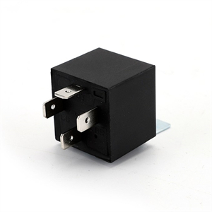
Figure 10: 5 Pin Relay
Consider the 4 pin relay, a common yet pivotal electronic component. It's the muscle behind larger current loads, powering car starters and home lighting systems. We will analyze the 4 pin relay wiring diagram in detail. 4 pin relay wiring diagram is seemingly simple: four key pins. Two activate the coil; two—labeled COM (common contact) and NO (normally open contact)—form the contact points. Activation occurs when the coil receives the right current, awakening a small magnet. This magnet generates a magnetic field, a silent force that moves the switching components within the relay. A dance of physics: it either makes (closes) or breaks (opens) an electrical connection between the COM and NO pins, masterfully controlling the connected circuit.
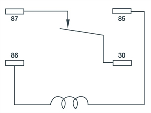
Figure 11: Normally Closed
(NC) 4 Pin Relay
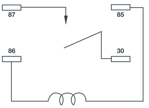
Figure 12: Normally Open
(NO) 4 Pin Relay
In practice, this 4 pin relay finds its stage in situations demanding remote or automatic control. Picture a car, where the relay whispers life into the engine, the coil closing the COM and NO connection, beckoning the current towards the starter. Or envision a home automation system, where relays orchestrate lights, receiving remote signals to flip circuits on or off. These diagrams, simple yet effective, are not just components. They are the unsung heroes in the realm of electronic parts, celebrated for their reliability and enduring construction.
The 5 pin relay, a paragon of efficiency in electronic control components, boasts a unique capability: it can control not just one circuit, but two distinct circuits simultaneously. This dual-circuit control gives it a significant edge in more complex applications. We will analyze the 5 pin relay wiring diagram in detail. In contrast to the 4 pin relay, which includes two coil pins and two contact pins (COM and NO), the 5 pin variant introduces an additional normally closed (NC) pin. This extra pin enables the relay to switch the circuit between two states—when the coil is inactive, the COM pin connects to the NC pin, and when the coil is active, it shifts to connect with the NO pin.
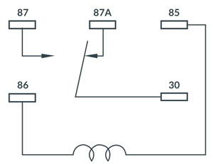
Figure 13: 5 Pin Relay Wiring Diagram
In practical scenarios, the 5 pin relay's adaptability makes it perfect for multi-functional control systems. Take a car, for instance: a single 5 pin relay can juggle control between the air conditioning and the audio system. Activating the coil switches the relay to manage the air conditioning; deactivating it reverts control to the audio system. This switchability not only boosts the system’s efficiency but also streamlines circuit design and cuts down on the number of necessary components.
The dual-state functionality of the 5 pin relay has also found widespread use in automation and intelligent control systems. In a smart home setup, for example, a single 5 pin relay can alternate between controlling the lighting and the security systems, automatically adjusting its operating status based on different scenarios. Such a wiring approach highlights the flexibility and versatility inherent in electronic component design and underscores the relay's significant role in the realm of modern electronic technology.
The 5 pin relay stands as an epitome of versatility and efficiency in the realm of electronic components. Its design, featuring two coil pins for activation and three single-pole double-throw (SPDT) switching function pins, embodies innovation. This unique setup empowers the relay to deftly alternate between Normally Open (NO) and Normally Closed (NC) contacts. This agility renders five-pin relays perfect for roles demanding swift circuit status changes, such as in high-speed data processing and emergency shutdown systems.
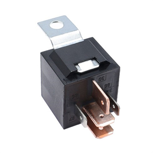
Figure 14: 5 Pin Relay
Applications of these relays span a spectrum. They range from straightforward single-pole single-throw (SPST) switches to the more intricate double-pole double-throw (2PDT) and four-pole double-throw (4PDT) switches. The 14 pin 4PDT relay, the most complex among its peers, offers abundant switching options. It is particularly suited for intricate circuit systems that necessitate multi-channel control.
In the automotive sector, the relevance of 5 pin relays is particularly pronounced. They empower small, in-vehicle switches to remotely command larger currents. This not only elevates circuit safety and reliability but also boosts the flexibility and efficiency of vehicle electronic systems. Consider the myriad functions in a car, lighting control, electric windows, sunroofs, seat adjustments, all relying on the efficient and precise control afforded by these relays.
Ensuring the correct connection of a 5 pin relay is paramount for its performance and safety. Let's take the Bosch 5 pin relay, a case in point. It features a single-pole double-throw (SPDT) switch design; its connection method is the linchpin for the entire circuit's functionality. Pins 85 and 86 are designated for the 12V coil connection – the heart of the power supply. The coil's energization state governs the interplay between pins 30, 87, and 87a.
The connection process involves more than just wiring the relay. It includes integrating it with the power supply, load, and switch. Here are the nuanced steps and precautions:
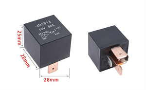
Figure 15: 5 Pin Relay
Connections for pins 85 and 86: These coil ends of the relay have specific roles. Pin 85 typically meets ground, while pin 86 connects to the control switch. The closing of the switch allows current through the coil, triggering the relay.
Pin 30 Connection: Connected to the power supply's positive terminal, this pin serves as the relay's normally open contact. It's pivotal in channeling current directly to either pin 87 or 87a.
Connecting pins 87 and 87a: As the working contacts, these pins have distinct states. With no power to the coil, pin 30 links to pin 87a. Once powered, the connection shifts from pin 30 to pin 87.

Figure 16: 5 Pin Relay Wiring Diagram
In automotive design, this method of connection is not just important – it's crucial. It directly impacts the stability and safety of the vehicle's electronic system. Take automobile starting systems, lighting control, and air conditioning systems, for instance. Here, precise relay connections are the key to accurate current distribution and control. They prevent circuit failures and mitigate safety risks.
Thus, mastering the correct connection of 5 pin relays is not merely a technicality. It's foundational for the safe and efficient functioning of electronic equipment. A thorough grasp of each pin's role and the right wiring approach is vital for any electronics project involving relays.
The 5 pin relay, renowned for its unique design, stands as a paragon of flexibility and versatility in the realm of high-end electronic systems. Its utility spans diverse scenarios. For instance, it proves invaluable in setting up a camera in a backlit environment, connecting an aftermarket amplifier, or providing additional power to high-current devices. Each application taps into the relay's distinct capabilities.
A graphical analysis sheds light on the specific function of each pin in these relays, illuminating their roles in varied applications. Let's delve into this analysis:
Pin 30 (normal contact): This is typically connected to the power supply's positive terminal, acting as the relay's main input. In any operational state, pin 30 remains active, directly influencing the relay's output.
Pins 85 and 86 (coil side): Used for activating the relay, pin 85 is usually grounded, while pin 86 connects to the control switch. Closing this switch energizes the coil, setting the relay in motion.
Pins 87 and 87a (working contacts): In active state, pin 87 forms a connection with pin 30. In contrast, pin 87a links to pin 30 when the relay is inactive. This dual capability allows the relay to manage different circuit paths under varying conditions.
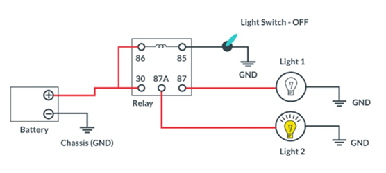
Figure 17: Wiring Diagram
for 5 Pin Relay: 5 Pin Relay Changeover Circuit
In practical terms, the applications of this relay are manifold. Take, for example, a camera in a backlit setting. Here, the relay swiftly toggles between different lighting sources, adapting to changing conditions. When integrating an aftermarket amplifier, the relay ensures power is supplied only when the vehicle starts, thus preventing battery drain. Similarly, in powering high-current equipment, its role pivots on controlling the safe distribution of substantial currents, assuring stable operation.
The schematic analysis of the 5 pin relay doesn't just aid our understanding of its internal structure and working principle. It also highlights its adaptability and broad usage across complex electronic systems.
The intricacies of relay application pivot crucially on the chosen trigger type—positive or negative. This decision governs the wiring method, an essential factor for both the relay's functionality and the overall circuit's safety and efficiency. Let's delve into the specifics.
In a positive trigger setup, pin 30 is directly linked to the power supply's positive terminal, usually safeguarded by a fuse. Such a connection primes the relay for activation upon receiving a positive voltage signal. Simultaneously, pin 86 finds its connection to the control switch, while pin 85 is typically grounded. Closure of the switch initiates the relay due to the current's journey from source to coil through the switch. This method is prevalent in systems where immediate relay activation is necessary upon detecting a positive voltage signal—think of a car's ignition or lighting control.
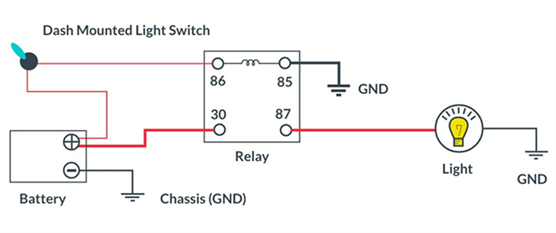
Figure 18: 4 Pin Relay with
Switch on Positive Side
Conversely, the negative trigger wiring adopts a different approach. Here, pin 85, not 86, connects to the control switch. Meanwhile, pin 86 forms a direct connection with the power supply's positive pole. This configuration leads to relay activation when a negative voltage signal, essentially a ground signal, is received. This method finds its place in scenarios requiring relay activation with the positive power signal off, like in certain security systems or automatic control systems.
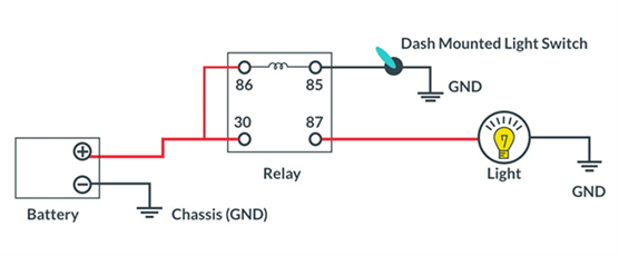
Figure 19: 4 Pin Relay with
Switch on Negative Side
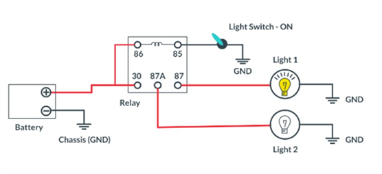
Figure 20: Wiring Diagram
for 5 Pin Relay: 5 Pin Relay Changeover Circuit - Negative Trigger
Understanding and correctly implementing these wiring schemes is paramount. It's not just about the relay's operation but also encompasses the entire circuit's design and intended function. In complex environments like automotive electronics or industrial automation controls, the choice of trigger method and precise wiring are vital. They are instrumental not only in ensuring the equipment's effective operation but also in upholding the system's safety and reliability.
In summary, whether dealing with positive or negative triggers, a deep comprehension of their mechanisms and mastering the art of wiring are indispensable for maintaining the efficiency and safety of electronic systems.
The 5 pin relay, while seemingly straightforward with its quintet of pins, harbors a rich complexity in its design nuances. These relays, varied in their coil design, contact ratings, and pin assignments, are tailored to meet a broad spectrum of application needs, making them a versatile staple in the world of electronics.

Figure 21: 5 Pin Relay
Varied Coil Designs: The relay's coil designs morph depending on voltage levels and power demands. For instance, some are crafted for low voltage, low power scenarios, whereas others thrive in high voltage, high power settings. This design malleability casts relays as pivotal components across diverse electronic systems.
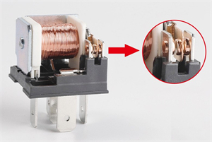
Figure 22: 5 Pin Relay
Contact Ratings Diversity: A relay's contact rating is pivotal, it dictates the maximum current and voltage it can handle safely. Needs differ; some high current applications demand relays with beefier ratings for safety and efficiency.
Pin Assignments: A Unique Twist: Every five-pin relay shares the commonality of five pins. Yet, it's in the distinct assignments and functions of these pins where differences emerge, tailoring specific relays to certain circuit types or applications.
Thus, the versatility of five-pin relays, while opening a door to myriad applications, also beckons for meticulous selection and application. Grasping each relay's unique characteristics and application scope is crucial. This understanding ensures not just the circuit's correct functioning but also enhances the safety and efficiency of the entire system.
In the field, choosing the right relay involves a holistic view, considering circuit requirements, the operating environment, and performance expectations. Indeed, the diversity of five-pin relays offers great flexibility and choice. However, this diversity also demands from engineers and technicians a deep understanding and stringent selection criteria. This approach ensures that every application achieves the best possible outcomes. Best results.
In the realm of today's automobiles and assorted mechanical devices, the incorporation of 5 pin relays is a ubiquitous standard, pivotal in controlling a myriad of electrical components. When malfunction looms, it often necessitates a thorough inspection, with the relay frequently under scrutiny as the potential culprit. This journey of diagnosis commences not haphazardly, but through a methodical series of steps, each critical in assessing the relay's functionality.
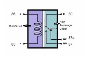
Figure 23: 5 Pin Relay Wiring Diagram
Delving into the heart of the matter, the coil's resistance emerges as a linchpin. It is this resistance that holds sway over the coil's performance and its overall stability. Coils, as integral components in electronic circuits, find their place in inductors or transformers, each with its unique role. Grasping the nuances of coil resistance, coupled with meticulous testing, is a cornerstone in ensuring the seamless operation and enduring reliability of electronic apparatuses.
Embarking on this exploration, the data sheet serves as an invaluable guide. Here, manufacturers delineate the standard resistance values of coils, along with their permissible tolerance ranges. Consider, for instance, a coil with a baseline resistance of 320 ohms and a tolerance of ±10%. This indicates an operational resistance spectrum ranging from 288 to 352 ohms – a range that accommodates the inevitable variances born from manufacturing processes and the inherent properties of materials used.
The act of measuring this resistance is deceptively straightforward. Begin by calibrating your digital multimeter to the ohm measurement mode. Then, engage the multimeter's probes with the coil's terminals, polarity concerns set aside in this resistance-centric endeavor. The reading that follows is pivotal: a value nestled within the 288 to 352 ohm bracket signals a coil in prime condition.
Conversely, deviations from this range – be it a striking drop below 288 ohms or a surge above 352 ohms – often herald the coil's demise. Such anomalies could stem from a spectrum of issues: insulation aging, overheating, mechanical wear and tear. Replacement typically stands as the go-to solution in these scenarios.

Figure 24: How to Test A 5
Pin Relay with A Multimeter: Testing 5 Pin Relay’s Coil Circuit
To contextualize with a tangible example, envision a wireless charger whose charging efficiency plummets unexpectedly. A thorough probe reveals the crux: prolonged use has eroded the internal coil resistance, culminating in an unwelcome increase. Here, coil replacement emerges as the salient, practical solution.
In essence, testing coil resistance transcends mere basic procedure; it is a critical facet in diagnosing electronic equipment malfunctions and maintaining their operational integrity. Armed with knowledge of theoretical resistance values, tolerance ranges, and adept measurement techniques, one can significantly bolster the stability and performance of a wide array of electronic devices.
Post verification of the coil's integrity, we pivot to the relay's terminals. The essence of this step lies in evaluating the resistance across the terminals of a standard 5 pin relay, encompassing:
12.2.1 Normally Open (NO) Terminal
Definition: In its quiescent state, the normally open terminal remains open, engaging only upon relay activation.
Detection Method: Assess the resistance between NO and the common terminal (COM). In its dormant state, these terminals should exhibit infinite resistance, contrasting starkly with near-zero resistance when the relay springs to life.
12.2.2 Normally Closed (NC) Terminal
Definition: The normally closed terminal, in contrast, remains closed in the relay's inactive state, only opening upon activation.
Detection Method: Measure the resistance between NC and COM. A functional relay, when not active, shows resistance close to zero here, but this flips to infinity once activated.
12.2.3 Common Terminal (COM)
Definition: Serving as the relay's fulcrum, the common terminal toggles between NO and NC.
Detection Method: The common terminal's inspection is typically intertwined with that of NO and NC, ensuring its seamless transition between connecting and disconnecting during the switching process.
12.2.4 Case Analysis
Consider, for instance, a home heating system reliant on relays for heater activation. A non-responsive heater, despite a thermostat's signal, hints at potential terminal faults, detectable through the aforementioned methods.
In the industrial sphere, relays orchestrate high-power motors. A malfunction here can cascade into significant production hiccups. Picture a scenario where an NC terminal fails to disengage properly, potentially leading to unceasing motor operation, a recipe for safety risks and equipment damage.
Inspecting relay terminals is not merely a procedural step; it is vital for the circuit's optimal functioning. By scrutinizing the resistance of NO, NC, and COM terminals, one can swiftly discern the relay's condition, paving the way for timely maintenance or replacement, thereby safeguarding the system's reliability.
12.3.1 Test Steps
Setting Up Your Multimeter: Initiate by configuring your digital multimeter to ohmmeter mode, a crucial step to measure the resistance across terminals effectively.
Connecting the Probes: Proceed by attaching the multimeter's probes, one to the common terminal (COM) and the other to the normally open terminal (NO). Remember, during resistance measurements, the probe's polarity is irrelevant; this eases the process.
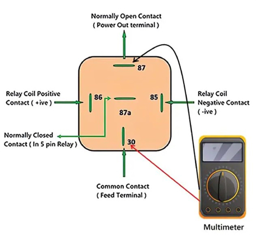
Figure 25: How to Test A 5
Pin Relay with A Multimeter: Tests High Current Circuits on 5 Pin Relay Common Terminals (COM) and Normally Open Terminals (NO)
Recording the Resistance Value: Key to this procedure, closely observe the multimeter's display, meticulously recording the resistance value. This reading is pivotal in assessing the status of the normally open terminal.
12.3.2 Interpretation of Resistance Values
Low Resistance Value: Ideal scenarios will show the normally open terminal's resistance as remarkably low, often in milliohms. This signifies a robust connection, allowing unimpeded current flow.
High Resistance Value: Contrastingly, an unusually high resistance reading suggests potential terminal issues—corrosion, looseness, breakage. Such high resistance impedes current flow, compromising relay performance.
Zero or Near-Zero Resistance Value: A resistance reading at zero or close to it could signify a shorted or damaged terminal, necessitating further inspection or replacement.
12.3.3 Case Analysis
Domestic Air Conditioning Systems: Relays are instrumental in powering compressors. For instance, a non-functioning air conditioner could hint at a relay fault, identified by testing the normally open terminal.
Industrial Control System: Consider a scenario where a high-power pump fails to start. Investigation might reveal that the relay's normally open terminal resistance is abnormally high, pointing to poor terminal contact, requiring cleaning or replacement.
Conclusion: Testing the normally open terminal is paramount for ensuring relay reliability. Accurate resistance measurements and interpretations are key to diagnosing and addressing relay issues, thus maintaining the stability of electronic systems.
12.4.1 Test Steps
Setting Up the Multimeter: Begin by adjusting your multimeter to ohms mode, a crucial preparatory step for accurate resistance measurement.
Connecting the Probe: Attach the multimeter's probe: one end to the normally closed terminal (NC) and the other to the common terminal (COM). In resistance measurements, thankfully, the polarity of the probe is not a concern.

Figure 26: How to Test A 5
Pin Relay with A Multimeter: Testing High Current Circuits on 5 Pin Relay Normally Closed Terminals (NC) and Common Terminals (COM)
Recording the Resistance Value: In the relay's inactive state, the resistance between the NC and COM terminals should hover near zero. It's at this juncture that you should take and meticulously record the resistance value.
12.4.2 Understanding the Importance of Resistance Values
Ideally Near Zero Ohms: In an optimal scenario, the resistance between the NC and COM terminals should be exceedingly low, verging on zero ohms. This low reading signifies a robust connection, enabling the unhindered flow of current when the relay is inactive.
High Resistance Values: Conversely, a high resistance reading signals potential issues at the normally closed terminal. Such resistance impedes current transfer in the relay's default state, potentially undermining the circuit's overall performance.
12.4.3 Practical Case Analysis
Automotive Electronic Systems: In practical applications, such as diagnosing faults in automotive electronic systems, the significance of NC terminal testing is paramount. For instance, consider a vehicle with a malfunctioning starter relay. Here, testing the NC terminals can swiftly pinpoint the issue. An abnormally high resistance reading may suggest poor internal contacts or damaged terminals, necessitating further inspection or replacement.
Efficiency and Safety: This method of detection empowers maintenance technicians to diagnose issues both swiftly and accurately. It mitigates time and cost wastage and is pivotal in ensuring the efficient and safe operation of automotive electronic systems.
12.5.1 Test Steps
Setting Up Your Multimeter: Begin by setting your digital multimeter to Ohms mode, a preparatory step essential for precise resistance measurements.
Connecting the Probes: Attach the multimeter probes to the two common terminals. Remember, in resistance measurements, the concern for probe polarity is effectively null.
Noting the Resistance Value: Ideally, the resistance between these common terminals should be minimal, hovering near zero. Vigilantly record the resistance value as shown on the multimeter.
12.5.2 Interpreting Resistance Values
Low Resistance or Near Zero: A resistance value that is strikingly low or approximating zero is indicative of a strong connection between the terminals, crucial for the relay's optimal function.
High Resistance Value: Conversely, an unusually high resistance reading can signal connection issues. These could range from poor terminal contact to corrosion or impurities disrupting the connection.
12.5.3 Case Analysis
Home Lighting System Example: Consider a scenario in a home lighting system relay test. An abnormal resistance value at the common terminal could stem from terminal looseness or corrosion, leading to malfunctioning lights.
Industrial Automation Control Systems: In these systems, the common terminals of relays bear significant responsibilities. Discovering high resistance during troubleshooting might hint at poor control signal transmission, impacting the entire production line. Timely detection, followed by cleaning or replacing problematic terminals, can swiftly resurrect system functionality, averting substantial production setbacks.
Conclusion: Testing common terminals is pivotal for ascertaining correct relay operation. Through meticulous resistance measurement and terminal status analysis, electrical issues can be efficiently identified and rectified, thus safeguarding system stability and safety.
12.6.1 Identifying Common Signs of Relay Damage
Abnormal Resistance: Testing each terminal's resistance in a relay can uncover potential issues. For instance, high resistance at a normally open terminal might signal a problem with the terminal or its coil.
Functional Failure: Another telltale sign is a relay's inability to switch correctly or respond to control signals, indicating potential damage.
12.6.2 Implementing Emergency Handling Methods
In real-world scenarios, when a relay's terminal, particularly the normally open one, malfunctions, consider these temporary solutions:
Thin Wire Connection: Facing high resistance at the normally open terminal? Temporarily connect the common terminal (COM) to the normally closed terminal (NC) using a thin wire. This makeshift solution keeps the circuit operational with the voltage off, buying time for a 5 pin relay replacement.
12.6.3 Steps for Relay Replacement
Safety First - Disconnect Power: Always ensure the power is entirely off before starting the relay replacement process.
Selection and Matching: Choose a new relay that aligns with the specifications of the original. It's crucial that the voltage and current specs meet the system's requirements.
12.6.4 Case Studies
Home Lighting System: Encounter a damaged relay rendering the lights uncontrollable? Use the described method for a temporary fix, then replace the relay to restore normal operation.
Industrial Control Systems: In these settings, relay failure can halt production. Applying temporary measures to maintain operations while swiftly replacing the relay can significantly reduce downtime and economic losses.
Conclusion: Although damaged relays typically necessitate replacement, prompt diagnosis and interim countermeasures can maintain system functionality, providing critical preparation time for a permanent solution. These steps are essential in swiftly resolving relay-related complications.
Delving into the multifaceted characteristics and applications of relays leads us to a definitive conclusion: their crucial role in automotive electrical systems and other high-current environments is undeniable. Relays, in their fundamental simplicity and efficiency, shine in reliability and versatility, especially within complex applications. The spotlight on five-pin relays, with their unique design and functionality, underscores an essential truth. Understanding and applying these components precisely is vital for the safety and operational efficiency of electrical systems.
In a world where science and technology advance at breakneck speed, the significance of relays is on an upward trajectory. Especially today, as we witness continuous strides in electronic component technology, the impact and importance of relays are set to escalate further. Their role in modern technology is not just significant—it's expanding.
Frequently Asked Questions [FAQ]
1. What is a Relay in a Circuit Diagram?
In the realm of circuit diagrams, a relay is depicted as an electrically operated switch, embodying a fascinating amalgamation of components: a coil, known as a magnet, an armature that functions as a switch, and one or more sets of contacts. The process is intriguingly simple yet pivotal. When current meanders through the coil, it doesn't just flow; it breathes life into a magnetic field. This field, in turn, springs the armature into action, leading to the pivotal opening or closing of the contacts. It's a dance of electricity and magnetism. The relay, thus, becomes a masterful mediator, controlling a high-power circuit with just a whisper of low-power signal, maintaining a crucial isolation between the two distinct circuits.
2. What are the Tests Done on Relays?
The reliability and functionality of relays are not left to chance. Rigorous tests weave their way through their evaluation:
The Pick-up Test, a critical assessment, pinpoints the minimum current that breathes life into the relay.
Then comes the Drop-out Test, revealing the current level at which the relay, like a performer exiting the stage, reverts to its normal state.
The Timing Test is next, a race against time, measuring the relay's response and actuation speed.
A crucial one, the Insulation Resistance Test, delves deep to ensure the relay's insulation integrity is uncompromised, guarding against the menace of short circuits.
Lastly, the Contact Resistance Test, ensures the contacts are not just good, but at their peak, offering minimal resistance, crucial for optimal performance.
3. What is a Relay for in Automotive Wiring?
In the intricate world of automotive wiring, a relay serves a critical role. It's the unseen hero, controlling high-current circuits—think of the demanding headlights, the whirring electric fans, or the indispensable fuel pumps—with just a low-current switch. This isn't just convenient; it's a safeguard. It means preventing high current from coursing through the vehicle's more delicate control switches and wiring, averting the risk of overheating, and steering clear of potential failure.
4. Why Would a Relay Need to be Installed in a Wiring Circuit?
In the intricate dance of electric circuits, a relay plays a pivotal role, its necessity born from several compelling reasons. Firstly, its primary function: enabling a low-power circuit to exert control over a more formidable high-power device - a David and Goliath scenario in electrical terms. Simplification of complexities follows; the relay is the unsung hero in reducing the need for cumbersome wiring and intricate switchgear. Then comes the guardian aspect – safety. Relays act as vigilant sentinels, providing an isolation layer between control and high-power circuits, a critical safeguard. Lastly, the element of adaptability – they imbue circuit design with much-needed flexibility, facilitating the integration of logic functions with an almost artistic finesse.
5. How Do You Read a Relay Circuit Diagram?
Deciphering a relay circuit diagram is akin to understanding a secret language, a blend of symbols and connections that unveil the circuit's story. The journey begins with the coil symbol, often depicted as a series of parallel lines, sometimes in a zig-zag pattern, a symbol that whispers the essence of the relay. Next, the eye searches for contact sets, those crucial pairs of lines or dots, each pair a storyteller, often labeled as 'normally open' (NO) or 'normally closed' (NC), revealing their default states. The narrative unfolds further as we trace the control circuit - the circuit's more subtle and understated part, typically linked to the coil. Contrastingly, we then encounter the load circuit, a depiction of the relay’s more powerful and commanding influence. And like any good story, there are often unexpected features – like time delays, each marked with their own unique symbols, adding depth and complexity to the already intriguing circuit diagram.


 ABOUT US
Customer satisfaction every time. Mutual trust and common interests.
 The Ultimate Guide to LM317 Transformers: Data, Characteristics, and Their Applications
 AG10 Battery,AG10 Battery Equivalent,AG10 Battery Replacement
 CL05C391JB5NNNC
 C1608X5R1E155M080AB
 06032U2R2BAT2A
 GCM1885C1H3R8CA16D
 GRM1885C2A681JA01J
 GRM0335C1E6R4DD01D
 TAP155K016SRW
 TBJA106K016CBSB0024
 DMN10H099SK3-13
 BLM21BD601SN1D