Practical Guide to Current Transformers: Construction, Types, Applications
2024-06-21
2420
Catalog
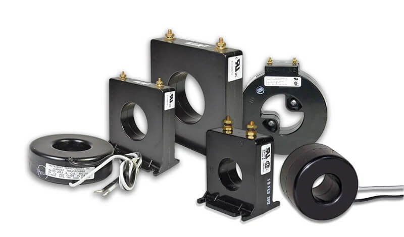
Figure 1: Current Transformer
What Are Current Transformers (CTs)?
Current transformers (CTs) are useful devices in electrical systems used for measuring and controlling current. Their main role is to transform large currents from power circuits into smaller, manageable levels suitable for standard measuring instruments & safety devices. This transformation not only allows for accurate current monitoring but also confirm safety by isolating high-voltage power systems from sensitive measuring equipment. CTs function based on magnetic induction. When a main electric current flows, it creates a magnetic field. This magnetic field then creates a smaller, matching current in a thinner, tightly wound wire. This process allows for accurate measurement of the current.
Current Transformers Construction
The construction of a current transformers is designed to meet its role in current sensing. Typically, the primary winding of a CT has very few turns—sometimes just one, as seen in bar-type CTs. This design uses the conductor itself as the winding, directly integrating it into the circuit that needs current measurement. This setup allows the CT to handle high currents while minimizing physical bulk & resistance.
On the other hand, the secondary winding comprises many turns of fine wire, making it suitable for converting high currents into lower, measurable values. This secondary winding connects directly to instrumentation, ensuring that devices like relays & meters receive accurate current inputs for proper operation. CTs are usually designed to output standardized currents of 5A or 1A at full primary current. This standardization aligns with industry norms, enhancing compatibility across various devices & applications. It also simplifies system design and helps in the calibration & maintenance of electrical measurement systems.
The insulation methods used in current transformers are customized based on the voltage levels they will handle. For lower voltage levels, basic varnish and insulating tape are often sufficient. However, in higher voltage applications, more robust insulation is needed. For high-voltage scenarios, CTs are filled with insulating compounds or oils to protect the electrical insulation under higher stress. In extremely high-voltage environments, such as transmission systems, oil-impregnated paper is used due to its superior insulating properties & durability. CTs can be designed in either live tank or dead tank configurations. The choice depends on the specific operational requirements of the installation environment. These configurations affect the transformer's physical stability, insulation needs, & ease of maintenance. Every aspect of CT construction is carefully considered to balance performance, cost-efficiency, and the specific needs of different electrical applications. These decisions guarantee safe operation across a range of conditions.
Working Principle of Current Transformers
Current transformers (CTs) are designed to measure and manage electrical currents accurately and reliably. They usually have a single primary winding connected in series with the load. For high-current scenarios, the primary winding is often a straight conductor, acting as a simple one-turn winding. This straightforward design efficiently captures high currents, avoiding the complexity & potential inaccuracies of multiple turns. This secures the CT remains sensitive and precise, providing exact current measurements in high-current environments.
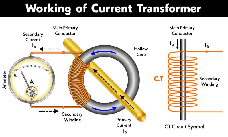
Figure 2: Working Principle of Current Transformer
For lower current applications, CTs use a primary winding with multiple turns wrapped around the magnetic core. This setup maintains the appropriate magnetic flux, which is required when connecting to power meters or other sensitive measurement devices. The multi-turn configuration allows CTs to adapt effectively to various electrical currents. That improves the safety and efficiency of power management systems.
The secondary winding, which is densely coiled around the core, has a specific number of turns to achieve an optimal turns ratio. This careful calibration minimizes the secondary’s influence on the primary current, isolating load changes & make sure accurate current measurements.
Current Rating of Current Transformer
The current rating of a current transformer (CT) defines its capacity to measure and manage electrical currents in power systems. Understanding the relationship between the primary and secondary current ratings helps for the correct application and functionality of the CT. The primary current rating determines the maximum current the CT can accurately measure, ensuring that the primary winding can handle these currents without risk of damage or performance loss. For example, a CT with a primary current rating of 400A can measure line loads up to this value.
The primary current rating directly influences the transformer's turn ratio, which is the ratio of turns between the primary and secondary windings. For instance, a CT with a 400A primary rating and a 5A secondary rating has an 80:1 ratio. This high ratio reduces high primary currents to a lower, manageable level on the secondary side, making measurements safer and easier. The standardized secondary current of a CT, rated at 5A, is important because it allows for the uniform use of measurement instruments & protection devices designed for a 5A input. This standardization enables safe and accurate monitoring of electrical systems without directly exposing instruments to high currents.
The 5A secondary rating simplifies the design and setup of associated electrical monitoring equipment. Instruments calibrated for a 5A output can be universally used across any system employing CTs, regardless of the primary current rating. This compatibility is beneficial in complex power systems with various CTs having different primary ratings. A CT's nameplate shows a ratio like 400:5, indicating its ability to transform a 400A primary current to a 5A secondary current. This rating informs users about the transformation ratio and helps in selecting the right CTs based on the electrical system's specific needs.
By understanding and applying these ratings correctly, users can guarantee that their electrical systems operate smoothly, with accurate measurements & effective protection mechanisms in place.
Specification of Current Transformers
Here are the key specifications for selecting the appropriate current transformer for various applications:
Current Rating - This specification determines the maximum primary current a CT can accurately measure. It confirms that the CT can handle expected current loads without risking performance or safety.
Accuracy Class - The accuracy class, indicated as a percentage, shows how precisely a CT measures primary current. This is helpful for applications requiring exact current measurement, such as power monitoring & billing.
Turns Ratio - The turns ratio specifies the ratio of primary to secondary currents. It confirms the secondary current is manageable for accurate measurement & safe monitoring.
Burden - The burden is the maximum load the secondary winding can handle without losing measurement accuracy. This makes certain the CT can drive connected devices like meters & relays effectively.
Insulation Level - This parameter specifies the maximum voltage the CT can withstand. It is used for maintaining safety and reliability, especially in high-voltage environments to prevent breakdowns.
Frequency Range - Defines the operational frequency range of the CT. It is utilized for ensuring compatibility with the system’s frequency & for accurate current measurement without frequency-induced discrepancies.
Thermal Rating - The thermal rating describes the maximum current CT continuously handle without exceeding a certain temperature rise. This is useful for preventing overheating & make sure long-term durability & safety.
Phase Angle Error - Measures the angular difference between the primary & secondary currents. Minimizing this error is required for high-accuracy applications to prevent incorrect readings & system inefficiencies.
Knee-Point Voltage - This is the voltage at which the CT starts to saturate, beyond which its accuracy drops. It is important in protection CTs for ensuring they trigger protective actions correctly.
Standards Compliance - Identify the industry standards a current transformer adheres to, such as IEC, ANSI, or IEEE. This confirms the CT meets international dependableness and safety benchmarks, for widespread use in power systems.
Accuracy at Different Loads - This specifies how a CT's accuracy varies under different load conditions. It guarantees consistent performance across a range of operational conditions for reliable functioning.
Types of Current Transformers
Current transformers (CTs) have various types categorized by construction, application, usage, and other characteristics.
Classification by Construction and Design

Figure 3: Window Current Transformers
Window Current Transformers - Window Current transformers have open circular or rectangular cores, allowing for non-invasive current monitoring. The primary conductor passes through the core, making it easy to monitor without disrupting the circuit. This design is ideal for quick, straightforward current assessments.
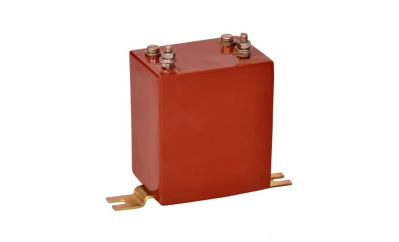
Figure 4: Wound Current Transformers
Wound Current Transformers - Wound current transformers have primary coils made of coiled windings, allowing for customizable ratios & current ratings. They are ideal for precise measurement needs in applications, such as protection devices.

Figure 5: Bar Type Current Transformers
Bar Current Transformers - Bar Current transformers feature one or more conductive bars. Known for their durability and simplicity. They are suitable for continuous current monitoring in branch circuits or power equipment.
Classification by Application and Installation Environment
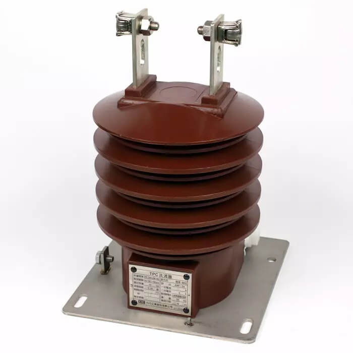
Figure 6: Outdoor Current Transformers
Outdoor Current Transformers - Outdoor current transformers are built to withstand various climates. Thay have a robust insulation and protective measures that guarantee solid performance in outdoor conditions.
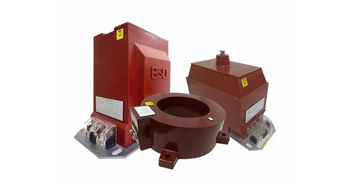
Figure 7: Indoor Current Transformers
Indoor Current Transformers - Indoor current transformers come with enclosures and insulation designed to meet indoor safety standards. That design confirms toughness in controlled environments.
Bushing Current Transformers - Installed within the bushings of high-voltage equipment, bushing current transformers monitor & regulate internal current flows in high-voltage systems.
Portable Current Transformers - Portable current transformers are lightweight and adaptable, used for temporary setups. They offer flexibility for emergency measurements or field assessments.
Classification by Usage and Performance Characteristics
Protection Current Transformers - Designed to detect over-currents and short circuits. Protection current transformers quickly activate protective measures to prevent system failures & equipment damage.
Standard Measuring CTs - Used across industries for metering and monitoring. These current transformers provide precise current measurement within their rated ranges for effective energy management.
Classification by Circuit Status
Open Circuit CT - Open circuit current transformers are primarily used for monitoring, allowing direct connection to measuring systems without needing to close the circuit.
Closed Loop CT - Closed loop current transformers maintain a closed circuit between primary and secondary windings. That enhance performance & impedance matching. They are ideal for high-accuracy applications.
Classification by Magnetic Core Structure
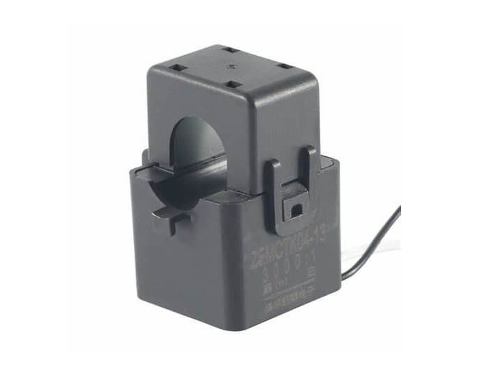
Figure 8: Split Core Current Transformer
Split Core Current Transformer - Split core current transformers have a core that can be opened, enabling easy installation around existing wires without disrupting circuits. They are perfect for retrofitting & maintenance.
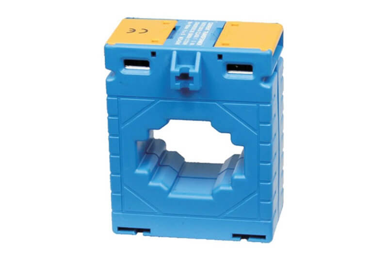
Figure 9: Solid Core Current Transformer
Solid Core Current Transformer - Solid core current transformers have a continuous core & are favored in high-accuracy applications where uniform magnetic field distribution is needed.
Classification by Managed Current Type
AC Current Transformer - Designed for AC power systems. These current transformers measure & monitor alternating currents effectively, typically featuring an iron core for optimized performance.
DC Current Transformer - Specialized for DC systems. This current transformer manages the unique properties of direct currents.
Types According to Cooling Method
Oily Type Current Transformer - These high-voltage CTs use oil for insulation, offering superior insulation properties but requiring careful maintenance.
Dry Type Current Transformer - Dry type CTs use solid insulation materials. They are typically used in low-voltage environments where cost-efficiency is a priority.
Classification by Voltage
LV Current Transformer - Low voltage (LV) current transformers are commonly used in commercial & industrial settings for detailed power monitoring & management.
MV Current Transformer - Medium voltage (MV) current transformers operate in medium voltage ranges, needed for bridging high and low-voltage networks in energy transmission applications.
Applications of Current Transformers
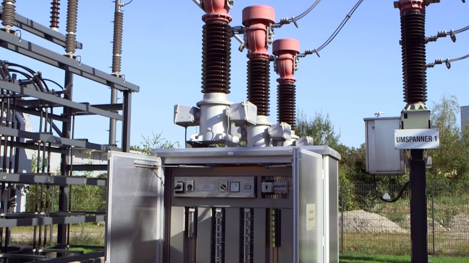
Figure 10: Current Transformer Applications
Current transformers (CTs) are used across various industries. Their versatility spans industrial, medical, automotive, and telecommunications sectors. Some are the following uses of CT:
Enhancing Measurement Capabilities
Current transformers expand the capabilities of instruments like ammeters, energy meters, KVA meters, and wattmeters. They allow these devices to measure a broader range of currents accurately. It also provides detailed monitoring & control of power usage and system performance.
Role in Protection and Monitoring
CTs are practical in protection systems within power transmission networks. They are used in differential circulating current protection systems, distance protection, & over-current fault protection. These systems rely on current transformers to detect abnormal changes in current flow, preventing equipment damage and power outages. Thereby, guarantee a stable power grid.
Power Quality and Harmonic Analysis
This function is increasingly applicable as modern electronic devices can introduce noise & harmonics that disrupt power quality. By identifying these disturbances, current transformers enable corrective measures to make sure dependable power delivery.
Specialized Applications in High-Voltage Environments
In high-voltage settings like substations and HVDC projects, current transformers are used in AC and DC filters within substations. They improve the efficiency of high-voltage power transmissions. Besides, current transformers also serve as protective devices in high-voltage mains & substations, safeguarding infrastructure against current surges and faults.
Integration in Capacitive Banks and Circuit Boards
Current transformers are integral to capacitive banks, acting as protection modules to monitor & manage electrical flow and stability. In electronic design, CTs are employed on printed circuit boards to detect current overloads, identify faults, & manage current feedback signals.
Monitoring and Managing Three-Phase Systems
CTs are widely used in three-phase systems to measure current or voltage. They help in monitoring and management of these systems in industrial and commercial settings. Particularly useful in power metering, motor current monitoring, & variable-speed-drive monitoring, all contributing to effective energy management and operational safety.
Advantages and Disadvantages of Using Current Transformers
Current transformers (CTs) offering numerous benefits that enhance safety & efficiency. However, they also have limitations that can affect their suitability in certain conditions.
Advantages of Current Transformers
Accurate Current Scaling - Current transformers can scale down high currents to safer, manageable levels for measurement instruments. This precise scaling is useful for applications requiring accurate data for operational efficiency & safety, such as power metering and protective relaying systems.
Enhanced Safety Features - Current transformers allow for current measurement without direct contact with high voltage circuits. It reduces the risk of electrical shocks & guarantee operator safety, especially in high-voltage environments.
Protection for Measurement Equipment - By protecting measurement instruments from direct exposure to high currents, current transformers extend the lifespan of these devices & maintain the accuracy of the data collected over time.
Reduction in Power Loss - Current transformers facilitate precise current measurements at lower levels, helping to identify inefficiencies, reduce power wastage, & promote cost savings and sustainability.
Real-Time Data Provision - CTs provide real-time data. It allows operators and engineers to make informed, timely decisions. This capability can help for preventing issues and optimizing system performance.
High Compatibility - Current transformers are compatible with a wide range of measurement instruments, serving as a universal interface for electrical monitoring systems.
Simplified Maintenance - Remote monitoring capabilities of CTs reduce the need for physical inspections, lower maintenance costs, and allow for quicker responses to detected anomalies.
Disadvantages of Current Transformers
Saturation Risks - Current transformers can become saturated if exposed to currents exceeding their design limits. That leads to non-linear performance & inaccurate readings, especially in systems with wide current fluctuations.
Challenges with Physical Size - Higher capacity current transformers are often bulky and heavy, complicating installation in compact spaces or retrofit scenarios.
Limited Bandwidth - Current transformers accuracy can vary with frequency changes, impacting performance in applications with variable frequency drives or other non-linear loads.
Maintenance Demands - Although CTs generally require less routine maintenance, they still need periodic calibration to maintain accuracy over time. Neglecting this can lead to performance degradation & reliability issues.
Factors to Consider When Selecting Current Transformers (CTs)
Here are the key factors to consider when choosing the right current transformer:
Compatibility with Primary Current Range - Ensure the CT's primary current range matches the highest expected current in the application. This prevents saturation and maintains accuracy, allowing the CT to handle maximum currents without risking performance issues.
Output Requirements of Metering Equipment - The secondary output of the CT must align with the input specifications of the connected metering devices. This compatibility prevents measurement errors and potential damage. Hence, guarantee accurate data collection and maintaining system integrity.
Physical Fit & Size Efficiency - The CT should fit comfortably around the conductor without being too tight or too large. A properly sized CT prevents damage to the conductor & avoids inefficiencies in cost and space usage.
Application-Specific CT Selection - Choose a CT based on its intended application. Different CTs are optimized for various uses, such as high-accuracy measurements, fault detection, or extreme temperature operation.
Rated Power Specification - The rated power, or burden rating, indicates the CT's capability to drive the secondary current through the connected load while maintaining accuracy. Make sure the CT's rated power matches or exceeds the total burden of the connected circuit for accurate performance under all conditions.
Precautions When Using Current Transformers
Proper precautions are required for current transformer’s safe and effective operation. Following these guidelines helps prevent transformer damage, guarantee accurate readings, and improves personnel safety.
Ensuring Secondary Circuit Safety
Keep the secondary circuit closed at all times. An open secondary can generate dangerously high voltages, leading to damage or hazardous arcing. When disconnecting an ammeter or any device from the secondary, short-circuit the terminals immediately. Use a low-resistance link, typically below 0.5 ohms, to safely redirect the current. Installing a short-circuiting switch across the secondary terminals is also recommended. This switch safely diverts current during connection changes or maintenance, preventing accidental open circuits.
Cooling and Grounding Requirements
CTs used on high-voltage lines often require cooling for safe operation. High-power CTs commonly uses oil cooling to dissipate heat and provide additional insulation for internal components. This cooling mechanism extends the transformer's lifespan and improve performance during continuous operation.
Grounding the secondary winding is another safety measure. Proper grounding diverts unintended voltages to the earth, reducing the risk of electrical shocks to personnel. This practice is needed for maintaining a safe work environment and mitigating risks associated with electrical faults.
Operating Within Specified Limits
Avoid operating CTs beyond their rated current to prevent overheating and damage. Exceeding the limit can cause measurement inaccuracies & compromise the CT’s structural integrity. The primary winding should be compact to minimize magnetic losses.
Pay attention to the secondary design as well. It should typically carry a standard current of 5A, aligning with common specifications for compatibility with most monitoring & protection equipment. This standardization makes sure consistent performance across different electrical systems & simplifies the integration of CTs into existing setups.
Maintenance of Current Transformers
Maintaining current transformers (CTs) will guarantee longevity and performance in accurately measuring electrical currents. Establishing a comprehensive maintenance routine helps identify potential issues early, extends the lifespan of CTs, and confirm they function within their intended specifications.
Regular Inspection
Conduct regular inspections to maintain CTs effectively. Periodic checks should focus on detecting any signs of wear, corrosion, or damage. Inspect the transformer for insulation breakdown, structural integrity of the casing, & signs of overheating. Address any anomalies promptly to prevent further damage & maintain the CT's functionality. Set up a routine inspection schedule based on the CT's operational environment and usage frequency to keep them in optimal condition.
Maintaining Cleanliness
Keep CTs clean for optimal performance. Dust, dirt, and other contaminants can disrupt the magnetic fields necessary for CT operation, leading to inaccurate readings. Regularly clean CTs with soft, non-abrasive materials and appropriate cleaning agents that are non-conductive to avoid damaging the transformer’s surface.
Ensuring Secure Connections
Secure electrical connections for the accurate operation of CTs. Loose connections can cause measurement errors and pose safety risks like electrical fires or system failures. Regularly check all connections, including terminal screws, wiring, and connectors, to make sure they are secure. Correct any loose connections immediately to maintain good system performance.
Temperature Management
Operate CTs within their specified temperature range to prevent damage. High temperatures can degrade or destroy internal components, leading to inaccurate measurements or irreversible damage. Monitor the ambient temperature where CTs are installed to check it remains within manufacturer-specified limits. Implement cooling measures or adjust the installation location if CTs are exposed to high temperatures to mitigate heat exposure.
Emergency Preparedness
For applications requiring continuous monitoring and operation, keep spare CTs on hand to minimize operational disruptions in case of CT failure. Having spare units guarantee that any malfunctioning CT can be quickly replaced, reducing downtime & maintaining continuous system functionality. This approach also allows for regular maintenance and repairs without compromising overall system performance.
The Difference Between Current Transformers (CTs) and Potential Transformers (PTs)
Understanding the distinctions between current transformers (CTs) and potential transformers (PTs) can help electrical engineers and professionals in related fields. This guide explores the key differences in their connection methods, functions, windings, input values, and output ranges.
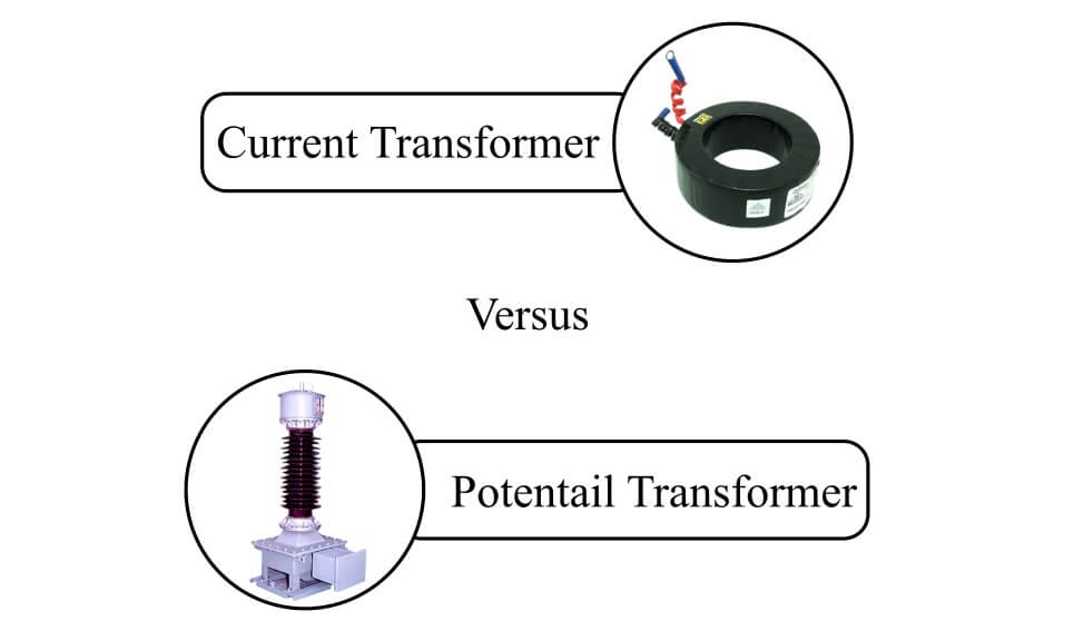
Figure 11: Current Transformer and Potential Transformer
Connection Methods
CTs and PTs connect to circuits in different ways. Current transformers are connected in series with the power line, allowing the entire line current to pass through their windings. This setup is needed for directly measuring the current flowing through the line. In contrast, potential transformers are connected in parallel with the circuit, enabling them to measure the full line voltage without impacting the circuit's characteristics.
Primary Functions
The main function of a current transformer is to transform high currents to safer, manageable levels for measurement devices like ammeters. CTs typically convert large primary currents down to a standardized output of either 1A or 5A, facilitating safe and precise current measurements. Conversely, potential transformers reduce high voltages to lower levels, typically to a standard secondary voltage of 100V or less, allowing for safe voltage measurements.
Windings Configuration
The winding design of CTs and PTs is tailored to their specific tasks. In CTs, the primary winding has fewer turns and is designed to handle the full circuit current. The secondary winding contains more turns, enhancing the transformer's ability to accurately step down the current. Potential transformers, however, feature a primary winding with more turns to manage high voltage, while the secondary winding has fewer turns to reduce the voltage to a practical level for measuring devices.
Input Value Handling
CTs and PTs manage different input values. Current transformers handle a constant current input, transforming it to a lower, standardized value without altering its proportionality. Potential transformers handle a constant voltage input, reducing this voltage to a safer, standardized value that accurately represents the original voltage, making it easier to measure.
Output Range Specifications
The output ranges of CTs and PTs differ to suit their respective functions. Current transformers typically provide outputs at 1A or 5A, aligning with the standard requirements of current measurement tools. Potential transformers generally produce an output voltage around 110V, designed to reflect the voltage conditions of the power system in a reduced yet manageable form.
Conclusion
As we've explored the ins and outs of current transformers, it's clear how significant they are for our electrical systems. From homes to huge power stations, these tools help keep our electricity flowing accurately and without harm. They manage large currents, protect expensive equipment, and ensure our systems run proficiently. Understanding current transformers means we can better appreciate the unseen work that goes into powering our daily lives.
Frequently Asked Questions [FAQ]
1. How do you operate a current transformer?
To operate a current transformer, you need to install it in series with the circuit where you want to measure the current. The primary conductor (carrying the high current you want to measure) should pass through the center of the transformer. The secondary winding of the transformer, which has more turns of wire, will produce a lower, manageable current proportional to the primary current. This secondary current can then be connected to measuring instruments or protection devices.
2. What is the primary use of a current transformer?
The primary use of a current transformer is to safely convert high currents from power circuits into smaller, measurable values that are safe to handle and suitable for standard measuring instruments such as ammeters, wattmeters, and protection relays. This allows for accurate monitoring & management of electrical systems without exposing equipment to high current levels.
3. Do current transformers increase or decrease current levels?
Current transformers decrease, or "step down," the current levels. They transform high currents from the primary circuit into lower currents in the secondary circuit. This reduction allows for safe & convenient measurement and monitoring by electrical devices that are designed to handle lower currents.
4. How can you tell if a current transformer is functioning properly?
To check if a current transformer is working correctly, observe the output from the secondary winding when there is current flowing in the primary conductor. Use a suitable meter to measure the secondary current, and compare it with expected values based on the transformer's specified ratio. Besides, check for any signs of physical damage, overheating, or unusual noise, which could indicate internal faults.
5. Where do you install a current transformer in a circuit?
A current transformer should be installed in series with the circuit that is being monitored or controlled. Typically, it is placed where the main power line enters a building or facility to measure the total incoming current. It can also be installed at various points along a distribution network to monitor current flow in different sections or branches of the network.
 ABOUT US
Customer satisfaction every time. Mutual trust and common interests.
function test. The highest cost-effective products and the best service is our eternal commitment.
Hot Article
- Are CR2032 and CR2016 Interchangeable
- MOSFET: Definition, Working Principle and Selection
- Relay Installation and Testing, Interpretation of Relay Wiring Diagrams
- CR2016 vs. CR2032 What’s the difference
- NPN vs. PNP: What's the Difference?
- esp32 vs stm32: which microcontroller is better for you?
- LM358 Dual Operational Amplifier Comprehensive Guide: Pinouts, Circuit Diagrams, Equivalents, Useful Examples
- CR2032 VS DL2032 VS CR2025 Comparison Guide
- Understanding the Differences ESP32 and ESP32-S3 Technical and Performance Analysis
- Detailed Analysis of RC Series Circuit
 The Essential Guide to 1K Ohm Resistors: Characteristics and Uses
2024-06-21
 Everything You Need to Know About Daughter Boards
2024-06-20
Hot Part Number
 C1608CH2A222K080AA
 UMK105CG820JV-F
 CGA5L2C0G1H104J160AD
 GJM0335C1E5R2DB01D
 GJM0225C1E7R3CB01L
 TMK063CH070FP-F
 GRM2196R1H561JZ01D
 T322D476K006AT
 IRFH7932TRPBF
 NFM21CC222R1H3D
- DS1080LU+T
- PIC16C717T-I/SO
- XC4010XL-3TQ144C
- TPS65910AA1RSL
- AD7865BSZ-3
- TPS54560BQDDARQ1
- OPA4227UA/2K5G4
- TPS92692QPWPTQ1
- TPS51623RSMR
- UCC3819D
- ADSP-21161NKCAZ100
- IDT7024S15PF
- AD7848JP
- ADM8628-AA-T-1
- AT27LV520-70SI
- AT89LV52-12QC
- BSC016N04LSG
- CASTSAMPLESL/1.1
- CAT28F010GI-90
- HPMX-2005-T10
- IDT723631L15PF
- LMH1981MT
- LP2951C3.3
- M37540M2-379GP
- MAX909EEE
- MT6325V/A
- RD520501FN
- S3P821AXZZ-TWRA
- SI9111DY
- TC74VHCT9273FT
- SAA3010T
- MT3351NA
- BD9721FV-E2
- BSN6040AGHZ
- HYB514400BT-70
- L50282B37NO
- OM6252CX9/1
- FA3675F-H1
- 5PB1108CMGI8