From Theory to Practice: Utilizing Zener Diodes for Reliable Overvoltage Protection
2024-05-15
9244
Catalog
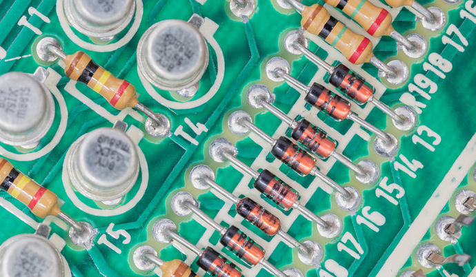
Figure 1: Zener Diode in Real PCB
What Is Zener Diode?
Zener diodes take advantage of the breakdown characteristics of the PN junction when reverse-biased, and can play a greater role in maintaining the stability of their terminal voltages when the current fluctuates significantly. The voltage of the diode across them remains constant and unaffected by any variations in the input voltage. This stability is useful in electronic circuit designs to counteract changes in circuit voltage that may result from power supply fluctuations or similar disturbances. By deploying Zener diodes at strategic points, designers can reliably stabilize the voltage across loads, ensuring consistent performance of the electronic components. This straightforward but sophisticated function of Zener diodes makes them an integral part of modern circuitry, facilitating precise control over voltage and enhancing the overall reliability of electrical systems.
In addition, the electrical symbol of the Zener diode is different from the ordinary diode symbol. In circuit diagrams, conventional diodes, such as signal diodes or power diodes, are depicted with standard symbols that differ from those used for Zener diodes.
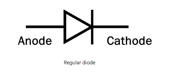
Figure 2: Regular Diode
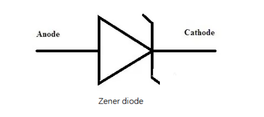
Figure 3: Zener Diode
When it comes to Zener diodes designed specifically for transient voltage suppression (TVS), these are often combined into a single device. This combination device is represented in schematics with a distinct symbol that visually differentiates it from single Zener diodes and other types of diodes. This specialized symbol helps technicians and engineers quickly identify the device's function and characteristics in a circuit, ensuring accurate and efficient circuit design and troubleshooting.

Figure 4: Combination of Two TVS Zener Diodes
Common Zener Diode Values and Part Numbers
When choosing a Zener diode, it’s crucial to pick one with a voltage rating that matches the needs of your circuit to ensure effective voltage regulation and protection. Here’s a breakdown of commonly used Zener diodes, their typical applications, and part numbers.
3.3V 1N5226
Ideal for stabilizing voltage in 3.3V logic circuits, which are commonly found in microcontrollers and digital signal processors (DSP). These diodes ensure consistent performance by maintaining the correct operating voltage.
5.1V 1N5231
Frequently used in 5V digital and logic circuits, this diode is perfect for typical TTL (Transistor-Transistor Logic) and CMOS (Complementary Metal-Oxide-Semiconductor) circuits. It provides reliable voltage regulation, safeguarding sensitive electronic components from voltage fluctuations.
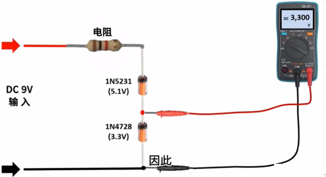
Figure 5: 1N5231 Zener Diode Measurement
6.8V 1N5235
This diode is tailored for analog circuits that operate slightly above 5V, offering additional protection for specialized sensors or older logic ICs (Integrated Circuits) that require a buffer in voltage to operate safely and effectively.
9.1V 1N5239
Optimal for 9V battery-powered devices, such as portable amplifiers or wireless modules. It ensures that these devices receive a stable power supply, enhancing their performance and reliability.
11.0V 1N5241
Suitable for circuits needing a voltage slightly above standard logic levels, including certain analog circuits. It also provides overvoltage protection for 12V systems, making it versatile for a range of applications.
13.0V 1N5243
Commonly used in 12V power supply systems, especially in automotive electronics or industrial control systems. It offers robust overvoltage protection, safeguarding against potential voltage spikes that could damage the system.
15.0V 1N5245
This diode is used where 15V voltage stability is necessary, such as in power supplies for operational amplifiers or as basic protection in electronic systems with higher operational voltage levels.
Working Principle of Zener Diode
The Zener diode operates on principles distinct from typical semiconductor diodes due to its unique physical structure, featuring heavy doping. This doping results in a considerably thinner depletion region, making the electric field more intense compared to that in ordinary diodes.
When a Zener diode is reverse-biased, the strong electric field within its narrow depletion zone can directly excite valence electrons to the conduction band at a specific voltage known as the Zener voltage. This direct excitation leads to Zener breakdown, a phenomenon distinct from the avalanche breakdown typically seen in less heavily doped diodes. In avalanche breakdown, the depletion region widens under reverse bias until the reverse voltage is high enough to energize minority carriers. These carriers gain enough energy to collide with lattice ions, liberating more electrons and setting off a chain reaction that sharply increases current.
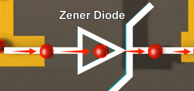
Figure 6: Zener Diode Forward Current
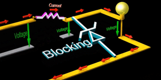
Figure 7: Principle of Zener Diode Overvoltage Protection Circuit
Zener breakdown, however, primarily stems from quantum tunneling caused by the intense electric field, occurring even before the conditions for avalanche breakdown are met. This critical difference allows the Zener diode to maintain a stable voltage across its terminals in the presence of varying current levels, a key characteristic that is leveraged in circuit design for voltage stabilization.
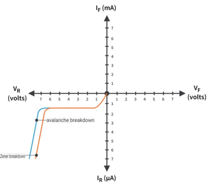
Figure 8: Zener Diode Zener and Avalanche Breakdown Diagram
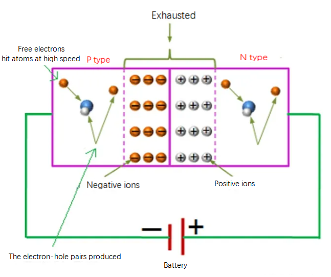
Figure 9: Schematic Diagram of Avalanche Breakdown of Zener Diode
For practical applications, Zener diodes are designed to utilize either Zener breakdown or avalanche breakdown, depending on their Zener voltage. Diodes with lower Zener voltages, typically under 6V, primarily undergo Zener breakdown, making them suitable for applications requiring voltage stability at lower voltages. Conversely, diodes with higher Zener voltages, over 6V, are more likely to experience avalanche breakdown, which is more suitable for handling higher voltage ranges. This flexibility allows Zener diodes to be employed across a broad spectrum of electronic applications, ensuring reliable voltage control and enhancing the overall adaptability of electronic circuits.
Difference between a Zener Diode and a Signal Diode
Zener diodes and signal diodes are semiconductor devices used in electronic circuits, but they differ significantly in function and structure, especially when reverse-biased.
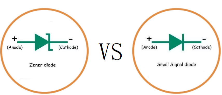
Figure 10: Zener Diode VS. Signal Diode
Zener Diodes—— Voltage Stability and Protection
These devices are specifically engineered to handle reverse bias conditions through heavy doping of the semiconductor material. This high doping level reduces the width of the PN junction, intensifying the electric field within the depletion region. As a result, when the reverse voltage reaches the Zener breakdown voltage (Vz), the Zener diode allows current to flow in the reverse direction without damage. This feature is crucial for applications such as voltage regulation and overvoltage protection, where maintaining a stable voltage or protecting sensitive components is necessary. For instance, in a voltage regulation scenario, when the circuit voltage exceeds the Zener voltage, the Zener diode activates, conducting current and stabilizing the voltage to prevent fluctuations that could damage electronic components.
Signal Diodes —— Efficient Signal Processing and Rectification
In contrast, signal diodes are designed for efficient forward conduction with minimal reverse current leakage. Typically, they allow very little current to flow when reverse biased—often just nanoamperes to microamperes—which is negligible for most applications. However, these diodes can be damaged if the reverse voltage exceeds their breakdown voltage, leading to potential open or short circuits. Their primary applications include signal shaping, switching, and low-power rectification, where forward conduction is necessary, and reverse current needs to be minimized to prevent interference.
While both Zener and signal diodes permit current flow from anode to cathode when forward-biased, their reverse-biased behaviors cater to distinct needs. Zener diodes are indispensable in circuits where voltage needs to be controlled or where components need protection against voltage spikes. Their ability to conduct in reverse without damage is unique and essential for such protective roles. Conversely, signal diodes excel in applications requiring efficient forward current conduction with robust isolation during reverse bias.
The choice between a Zener diode and a signal diode hinges on the specific requirements of the application—voltage stabilization and protection for the former, efficient signal handling, and rectification for the latter. Each type of diode offers tailored benefits that make them suited to different roles in circuit design and implementation.
Advantages and Disadvantages of Zener Overvoltage Protection Circuit (OVP)
Advantages
Firstly, a Zener overvoltage protection circuit is notably straightforward, consisting primarily of a Zener diode paired with a series resistor. This minimalistic design facilitates easy integration into various electronic setups, making it accessible even for those with basic technical skills. It is also easy to maintain due to the few components involved.
Next, using Zener diodes for overvoltage protection is economically advantageous. Both the diodes themselves and the associated components are inexpensive and widely available. This makes Zener diode circuits an attractive option for effective voltage regulation without a significant financial investment.
What's more, Zener diodes are designed to offer a stable output at their specified breakdown voltage. This stability is crucial for limiting voltage to safe levels, ensuring reliable protection against voltage spikes that could otherwise damage sensitive circuit components.
Disadvantages
One significant drawback is the circuit's tendency to consume considerable power during operation. As the Zener diode activates to clamp the voltage, it also allows current to pass, which generates heat due to resistance. This heat is essentially wasted energy, posing a challenge in energy-sensitive applications.
Then, the heat generated by the Zener diode when conducting can lead to higher temperatures within the circuit. Implementing additional cooling measures, such as heat sinks or fans, may be necessary to dissipate heat efficiently and maintain safe component temperatures.
However, While Zener diodes excel at voltage regulation, they do not inherently provide strong overcurrent protection. To safeguard against excessive currents that might occur during fault conditions, it is often essential to pair Zener diodes with other protective components like fuses or circuit breakers, which can complicate the circuit design and add to the cost.
The Function of Zener Diode
The primary function of an overvoltage protection circuit is to continuously monitor circuit voltage and respond swiftly if it exceeds the safety threshold, thus preventing potential damage to electronic components. Zener diodes play this role as well, as they can maintain stable conduction at a specific reverse breakdown voltage while exhibiting high resistance under normal operating conditions, ensuring that they do not interfere with the proper functioning of the circuit.
Firstly, identify the normal operating voltage and the maximum voltage threshold that could damage the circuit components. Choose a Zener diode with a Zener voltage slightly above the normal operating voltage but below the maximum voltage threshold. This setup ensures that the diode activates to conduct electricity only when the voltage exceeds the normal range, thereby protecting against overvoltage.
Secondly, Integrate the selected Zener diode into the circuit in parallel with the component it is meant to protect. Precise placement is required as it allows the diode to shunt excess voltage away from the sensitive component. Add a current-limiting resistor in series with the Zener diode. The purpose of this resistor is to control the flow of current through the diode when it is active, preventing damage due to excessive current and ensuring the circuit remains stable and safe under overvoltage conditions.
Operational Example
Consider a circuit designed for improved noise density measurement. Here, a Zener diode is placed after the low-noise power supply, with a breakdown voltage just over the typical supply voltage to handle any fluctuations. The Zener diode acts to absorb voltage spikes and stabilize the output voltage to subsequent circuits. A carefully calculated current-limiting resistor is used to protect the Zener diode under various load conditions and ensure consistent voltage output.
To handle noise signals, include a DC blocking capacitor to filter out DC components and allow only the AC noise signal through, ensuring it is free from DC interference. The noise signal is then amplified using a low-noise amplifier and possibly through multi-stage amplification to strengthen the signal without altering its integrity. This signal is then passed through a bandpass filter set between 1kHz and 3kHz to isolate and measure noise only within the target frequency range, thus ensuring precision in detection and measurement.
Finally, the signal is measured using a true RMS voltmeter, which offers high accuracy and stability. By carefully selecting the Zener voltage and configuring the current-limiting resistor, a Zener diode overvoltage protection circuit provides a robust solution for safeguarding electronic equipment from unexpected high-voltage events, thus ensuring the durability and stable operation of electronic devices.
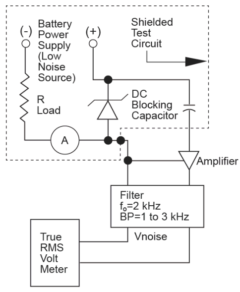
Figure 11: Zener Diode Used in Noise Density Measurement Circuit
How to Protect Circuits from Overvoltage?
Protecting sensitive electronic components, like microcontrollers, from excessive voltages is crucial in circuit design. Typically, microcontroller I/O pins have a maximum voltage tolerance — often 5V. Exceeding this limit risks damaging the microcontroller. A practical method to safeguard these components involves constructing an overvoltage protection (OVP) circuit using Zener diodes.
For a circuit where the normal operating voltage is near 5V, a Zener diode with a slightly higher breakdown voltage, such as 5.1V, is ideal. This ensures that under normal conditions (voltages below 5.1V), the Zener diode remains non-conductive and does not interfere with the circuit operation. When the input voltage exceeds 5.1V, the Zener diode activates, conducting current and clamping the voltage to approximately 5.1V to prevent any damage to the circuit components downstream.
To validate the design, simulate the OVP circuit using SPICE software, such as Cadence PSpice. Set up the simulation with a voltage source (V1), a current-limiting resistor (R1), and the chosen Zener diode (D2). In this scenario, assume a 6.8V Zener diode (e.g., 1N4099) for testing. If V1's voltage exceeds 6.8V, the simulation should show that the output voltage is effectively limited to around 6.8V or less, confirming the diode's protective capability.
With an input voltage of 6V, the output should remain stable and close to the input, indicating normal operation. At 6.8V, the output should align slightly below the Zener voltage, showing the diode's engagement and voltage stabilization. On increasing the input to 7.5V (an overvoltage condition), the output should stay significantly below the input, around 6.883V, demonstrating effective protection against overvoltage. Depending on the specific needs of the circuit, Zener diodes with various breakdown voltages like 3.3V, 5.1V, 9.1V, or 10.2V can be chosen. This flexibility allows designers to tailor the overvoltage protection to the precise requirements of the application, ensuring optimal protection.
By carefully choosing the appropriate Zener diode and accurately simulating its behavior under different voltage conditions, designers can ensure robust overvoltage protection. This approach not only prevents damage to delicate circuit components but also enhances the overall reliability and performance of electronic devices.
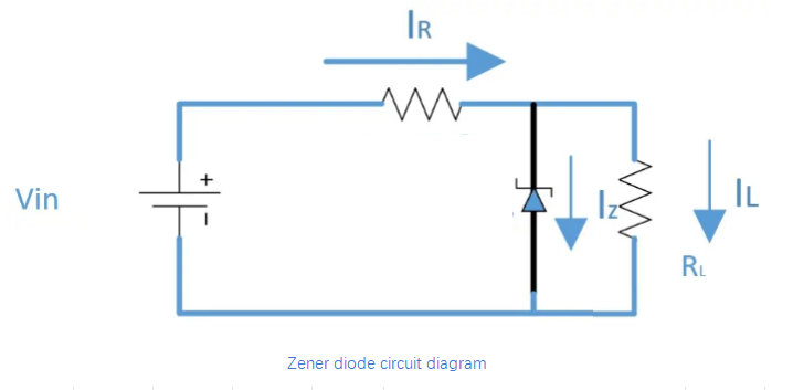
Figure 12: Zener Diode Circuit Diagram
How to Choose the Appropriate Overvoltage Protection Zener Diode?
Choosing an effective Zener diode for overvoltage protection requires a few critical steps to ensure the circuit operates safely and efficiently under all conditions.
Determine the Appropriate Zener Voltage
Identify the maximum voltage that the circuit should handle. For instance, if the design specifies that the voltage should not exceed 6.8V, a Zener diode with a breakdown voltage of 6.8V would be ideal.
If an exact match for the needed Zener voltage is not available, opt for the closest higher value. For example, to protect against overvoltages as high as 7V, a 6.8V Zener diode would be a suitable approximation, effectively clamping the voltage just below the maximum threshold.
Calculate Load and Bias Current
Start by calculating the current that will typically flow through the load; suppose it is 50mA. Add the bias current necessary for the Zener diode's operation to this figure. If the Zener diode requires a bias current of 10mA, the total current requirement would then be 60mA (50mA load current plus 10mA bias current).
Determine the Power Rating for the Zener Diode
Calculate the power dissipation using the Zener voltage and the total current. With a Zener voltage of 6.8V and a total current of 60mA, the power dissipation would be calculated as 6.8V x 0.060A = 0.408 watts. Select a Zener diode with a power rating higher than the calculated value to ensure reliability and safety. A diode with a 500mW rating would provide sufficient margin.
Compute the Value of the Current Limiting Resistor
Ascertain the maximum voltage the circuit might experience, say 13V. Calculate the voltage drop across the resistor, which is the difference between the source voltage and the Zener voltage: 13V - 6.8V = 6.2V. Using Ohm's Law, compute the resistance value needed: Voltage Drop / Total Current = 6.2V / 0.060A ≈ 103Ω. You can round this off to a standard resistor value like 100Ω for practical purposes.
Detection Method of Zener Diode
To identify the polarity of Zener diodes, one can start by examining their appearance. Metal-encapsulated Zener diodes often distinguish polarity through the shape of their end face: the flat end typically indicates the positive electrode, while the semicircular end marks the negative electrode. For plastic-encapsulated Zener diodes, look for a color mark on the negative terminal, offering a quick visual guide to polarity.
For a more precise method, using a multimeter set to the diode test or a low resistance setting, such as RX1k, is effective. Connect the multimeter probes to the diode—one to each terminal. Note the resistance displayed, then swap the probes and measure again. The setup that shows lower resistance will have the black probe on the positive and the red on the negative terminal. A very high or very low resistance in both measurements might indicate that the diode is damaged and not functioning correctly.
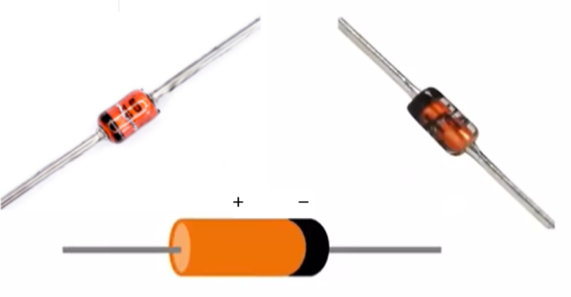
Figure 13: Zener Diodes
When measuring the voltage regulation value of a Zener diode, using a continuously adjustable DC power supply is advisable. For Zener diodes rated below 13V, set the power supply to 15V. Connect the diode in series with a 1.5kΩ current-limiting resistor between the cathode and the positive output of the power supply, and the anode to the negative output. Measure the voltage across the diode using a multimeter; the value displayed will be the diode's voltage regulation value.
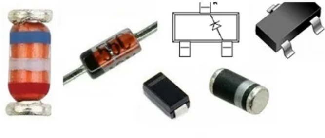
Figure 14: Common Zener Diode Shapes
For Zener diodes with regulation values above 15V, increase the power supply's output to over 20V to ensure accurate measurement. Alternatively, for high-voltage Zener diodes, a megohmmeter capable of delivering up to 1000V can be used. Connect the megohmmeter’s positive lead to the diode’s negative terminal and the negative lead to the positive terminal. Rotate the megohmmeter's handle at a consistent speed and read the voltage across the diode using a multimeter until it stabilizes at the diode’s regulation voltage.
If fluctuations or instability in the voltage value are observed during these tests, it could indicate that the diode is either performing inconsistently or is damaged, necessitating its replacement.
Zener Diode Package Size
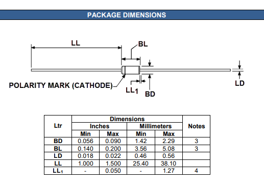
Figure 15: Zener Diode Package Dimensions
When working with Zener diodes, one must be familiar with their physical dimensions and packaging. The dimensions of these diodes are typically provided in inches, following certain manufacturing standards and industry preferences, although millimeter dimensions are also available for reference.
Package Outline Details
The outer dimensions of a Zener diode's package, which include both the diameter (BD) and length (BL), can be adjusted within specified limits. This flexibility allows for custom fitting in various applications, particularly when thermal management is a concern. If the Zener diode package includes thermal paste, used to enhance heat conduction away from the diode, this element should be considered in the total package size. However, the usual minimum size constraints for the diameter (BD) do not apply when the thermal paste is involved. The length measurement (BL) should encompass the entire package, thermal paste included.
Pin Diameter Variations
In Zener diodes, the diameter of the pins can differ within the package. This variation accommodates any irregularities in pin finish or deviations in sections that do not include thermal paste. Factors such as plating thickness or minor manufacturing anomalies can lead to differences in pin size, which are important to consider during the design and assembly processes.
Symbol Representation for Diameter
To ensure clarity in documentation and consistency across engineering designs, the diameter size in drawings and specifications for Zener diodes adheres to the ASME Y14.5M standard. This standard dictates the use of the "φx" symbol to represent diameters, promoting uniformity and precision in engineering drawings and helping maintain consistency in manufacturing specifications.
Conclusion
The development of Zener diodes has made them indispensable in modern electronics, especially in voltage regulation and overvoltage protection. Their unique Zener and avalanche breakdown properties enable them to handle voltage fluctuations effectively. Comparing their structures and operations with those of signal diodes deepens our understanding of their specific applications in circuit designs. However, while Zener diodes offer efficient, cost-effective overvoltage protection, they also present challenges such as high energy consumption and the need for effective thermal management. These issues highlight the necessity for ongoing innovation and optimization in electronic circuit design to leverage the full potential of Zener diodes.
Frequently Asked Questions [FAQ]
1. What is a Zener diode used for?
A Zener diode is primarily used for voltage regulation, ensuring that even if the supply voltage fluctuates, the voltage across the Zener diode remains stable. It is also used for overvoltage protection, protecting sensitive electronics from voltage spikes.
2. What is overvoltage protection?
Overvoltage protection is a circuit protection mechanism that prevents excessive voltage from damaging electronic components. It ensures that voltage levels remain within safe limits for the circuit's components.
3. What are the overvoltage protection circuits?
Overvoltage protection circuits are designed to prevent excessive voltage from reaching and damaging components. These circuits typically use components like Zener diodes, varistors, or transient voltage suppressor (TVS) diodes to clamp the voltage to safe levels during voltage spikes.
4. What is the difference between a normal diode and a Zener diode?
The main difference lies in the handling of reverse voltage. Normal diodes block current in the reverse direction and can be damaged if the reverse voltage exceeds a certain threshold. In contrast, Zener diodes are designed to not only block reverse current but also to safely conduct when the reverse voltage exceeds a predetermined level, known as the Zener voltage, without damage.
5. What is the working principle of Zener diode?
A Zener diode operates by allowing current to flow in the reverse direction when the voltage exceeds its Zener voltage. This is due to its heavily doped p-n junction which creates a narrow depletion region. The high electric fields at this junction allow the Zener diode to conduct in reverse without being damaged, thereby maintaining voltage stability across it. This property is utilized for voltage regulation and protection in circuits.
 ABOUT US
Customer satisfaction every time. Mutual trust and common interests.
function test. The highest cost-effective products and the best service is our eternal commitment.
Hot Article
- Are CR2032 and CR2016 Interchangeable
- MOSFET: Definition, Working Principle and Selection
- Relay Installation and Testing, Interpretation of Relay Wiring Diagrams
- CR2016 vs. CR2032 What’s the difference
- NPN vs. PNP: What's the Difference?
- esp32 vs stm32: which microcontroller is better for you?
- LM358 Dual Operational Amplifier Comprehensive Guide: Pinouts, Circuit Diagrams, Equivalents, Useful Examples
- CR2032 VS DL2032 VS CR2025 Comparison Guide
- Understanding the Differences ESP32 and ESP32-S3 Technical and Performance Analysis
- Detailed Analysis of RC Series Circuit
 Structure, Characteristics and Uses of P-Channel MOSFET in the Electronic Field
2024-05-16
 Understanding the 555 Timer IC: Functionality, Modes, and Technical Specifications
2024-05-15
Hot Part Number
 CGA6M3X7R2A155M200AB
 C4532JB3D222K130KA
 CC0201CRNPO9BN3R9
 GRM1885C1H5R9CA01D
 GJM0225C1E4R9CB01L
 CL05B105KQ5NQNC
 0402YC151KAT2A
 LD055C101KAB2A
 LD031C102JAB6A
 GRM1555C1H3R5CZ01D
- TAJR335K004RNJ
- TAJB475K020A
- L60030M2SQ
- SP12A1T
- ATMEGA8-16MUR
- MKE02Z64VLD2
- SP208ECT-L/TR
- ISL95832IRTZ-T
- LTC3603IMSE#TRPBF
- ADP50250017CBZR
- AD9240ASZ
- HMC1049LP5E
- CM1248-04QG
- T491C106M035ZTZV10
- LM431AIM3/NOPB
- ADV7393WBCPZ
- ADR4530BRZ-R7
- E-L6219DSA
- SN74AUC1G08DCKR
- HCF4051BEY
- LM9036QMM-5.0/NOPB
- AM79C984AKC/W
- TC74AC574AF
- UBA2211CT/N1
- UPD754302
- 71PL064JB0BFWQB
- AM7946-1JC
- FDC658P_NL
- HC4066AG
- JM20339-LGCA0C
- M59MR032C120GC6T
- MCM511000AJ7Q
- STMP3770XXLAEA30N
- BRF6150BGSL1R
- EDB5432BEPA-1DAAT-F
- BZX585-C5V1 115
- MJ-179PH
- LFCG-1575+
- BSS84PH6327